
Opposed flow high pressure-low pressure steam turbine

a steam turbine and high pressure technology, applied in the direction of non-positive displacement fluid engines, pump control, etc., can solve the problems of large number and diameter of stages, poor performance, and inability to take full advantage of the reaction mechanism in extracting energy, so as to improve the overall steam path efficiency, the effect of limiting the thrust and increasing the reaction ra

Active Publication Date: 2010-06-24
GENERAL ELECTRIC CO
View PDF8 Cites 7 Cited by
  • Summary
  • Abstract
  • Description
  • Claims
  • Application Information

AI Technical Summary

Benefits of technology

[0011]Accordingly, there is a need to provide an arrangement for a HP steam turbine and a LP steam turbine combination to advantageously limit thrust, so an overall steam path efficiency may be improved by increasing stage reaction.
[0012]The present invention relates to an arrangement for a HP steam turbine and a LP steam turbine combination to advantageously limit thrust, so an overall steam path efficiency for the combination may be improved by increasing stage reaction. Briefly in accordance with one aspect an opposed flow steam turbine is provided. The opposed flow steam turbine includes a high pressure steam turbine and a low pressure steam turbine. A rotor shaft is provided common to the high pressure steam turbine and the low pressure steam turbine. A first steam flow path is provided through the high pressure steam turbine. A second steam flow path is provided in an opposing direction through the low pressure steam turbine. Means are provided for directing the first steam flow path from the high pressure steam turbine to the second steam flow path in an opposing direction through the low pressure steam turbine.

Problems solved by technology

In large power steam turbines, the number and diameter of the stages become massive.
Historically, full advantage has not been taken of the reaction mechanism in extracting energy from the steam turbine, in part because turbine performance was considered adequate and in in part due to difficulty in responding to increased axial thrust on the rotor shaft resulting from increased reaction forces on the moving blades.
This is not a good performance combination as large thrust bearing means large bearing losses and low reaction means low steam path performance.
Such configurations have none or very little performance room to improve.
Increased stage reaction, however, leads to increased thrust loads necessitating greater thrust handling capability (reflected in greater size of the thrust bearing).
The size of the thrust bearings already restrict the performance of HP-LP single flow units forcing a low reaction steam path design around 5%.

Method used


Image

  • Opposed flow high pressure-low pressure steam turbine
  • Opposed flow high pressure-low pressure steam turbine
  • Opposed flow high pressure-low pressure steam turbine

Examples


Embodiment Construction

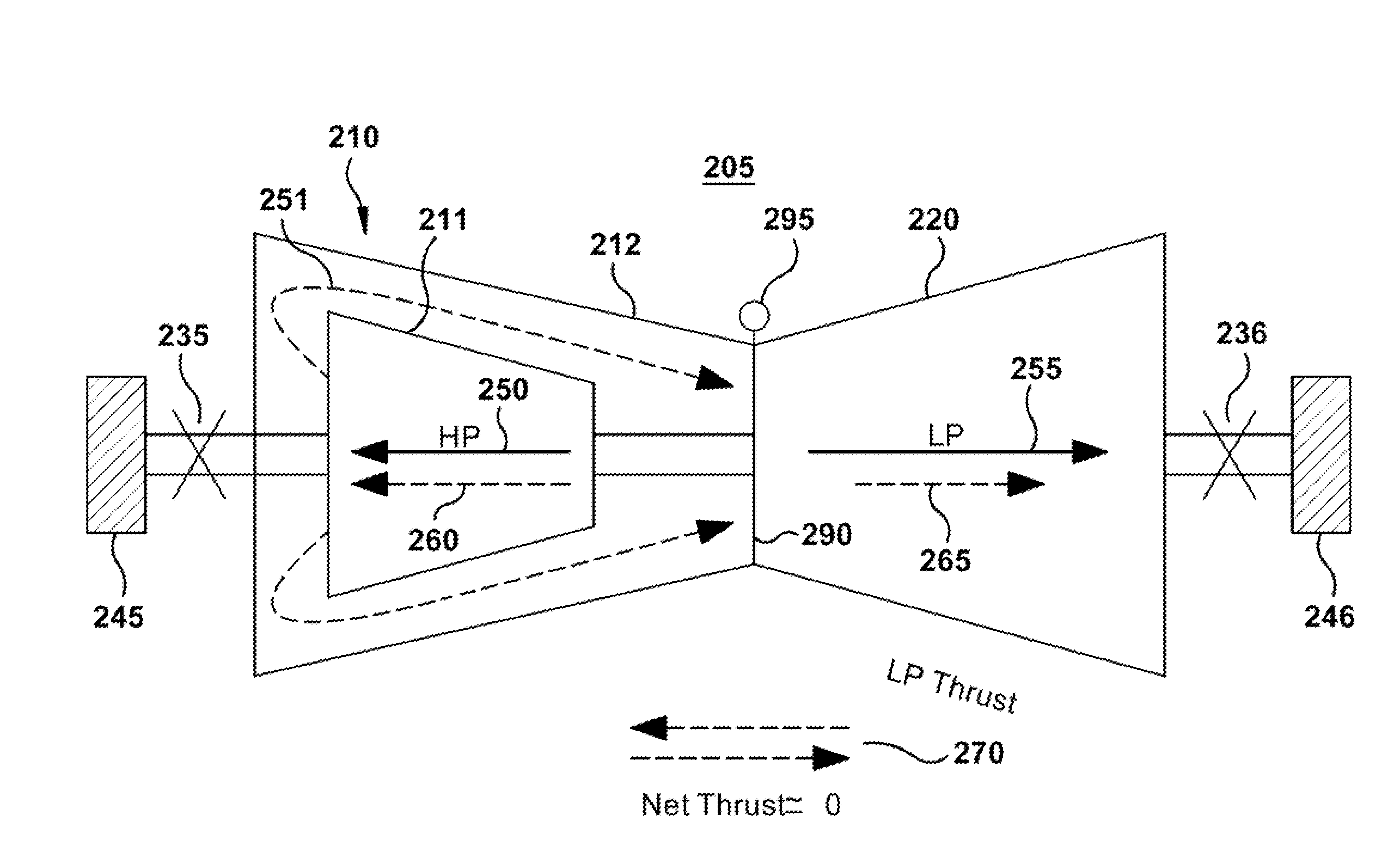
[0019]The following embodiments of the present invention have many advantages, including providing an opposed flow high pressure-low pressure steam turbine that balances thrust of the high pressure steam turbine with the thrust of the low pressure steam turbine allowing a reduction in size of thrust bearings. Higher stage reactions in both turbines may be incorporated since they are offset with the opposed flow, allowing a higher steam path efficiency. Opposed flow may be established through a cross-over pipe or utilizing a double high pressure shell. Analysis suggests a potential increase in HP steam path efficiency of at least 2% percent and an overall thrust load reduction of about 40%.

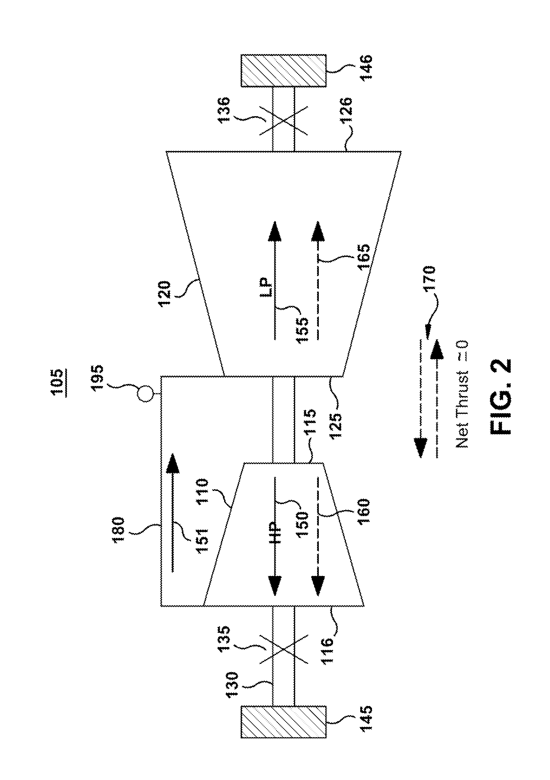
[0020]FIG. 2 illustrates one embodiment of the opposed flow steam turbine. The opposed flow steam turbine 105 includes a HP steam turbine 110 and a LP steam turbine 120. A rotor shaft 130 is provided common to the HP steam turbine and the LP steam turbine. A first steam flow path 150 is provided th...


PUM


Abstract

An opposed flow high pressure-low pressure steam turbine balances thrust of the high pressure steam turbine with the thrust of the low pressure steam turbine allowing a reduction in size of thrust bearings. Higher stage reactions in both turbines may be incorporated since they are offset with the opposed flow, allowing a higher steam path efficiency. Opposed flow may be established through a cross-over pipe or utilizing a double high pressure shell.

Description

BACKGROUND OF THE INVENTION[0001]The invention relates generally to steam turbines and more specifically to steam flow arrangements within the steam turbines to minimize thrust.[0002]Today, large steam turbines are often used for large combined cycle power systems having a steam turbine and gas turbine, together driving an electrical generator as the load. Many arrangements for gas turbines and steam turbines in a combined cycle have been proposed. A combined cycle is an integrated thermal cycle, wherein the hot exhaust gas from a combustion gas turbine contributes heat energy to partially or wholly generate the steam used in the steam turbine.[0003]A steam turbine is a mechanical device that extracts energy from pressurized steam, and converts the energy into useful work. Steam turbines receive a steam flow at an inlet pressure through multiple stationary nozzles that direct the steam flow against buckets rotationally attached to a rotor of the turbine. The steam flow impinging on ...

Claims


Application Information

Patent Timeline
Patent Type & Authority Applications(United States)
IPC IPC(8): F01D3/02
CPCF05D2240/52F01D3/02F01D1/04F01D1/16F01D17/00F01D25/16
Inventor HERNANDEZ, NESTOR
Owner GENERAL ELECTRIC CO
Features
  • Generate Ideas
  • Intellectual Property
  • Life Sciences
  • Materials
  • Tech Scout
  • Unparalleled Data Quality
  • Higher Quality Content
  • 60% Fewer Hallucinations
Learn More