
Posterior Cervical Cross Connector Assemblies

a cross connector and anterior cervical technology, applied in the field of spinal fixation devices, can solve the problems of sizing, locking and installation, height limitations, and ease of installation

Active Publication Date: 2010-06-24
LIFE SPINE INC
View PDF14 Cites 118 Cited by
  • Summary
  • Abstract
  • Description
  • Claims
  • Application Information

AI Technical Summary

Benefits of technology

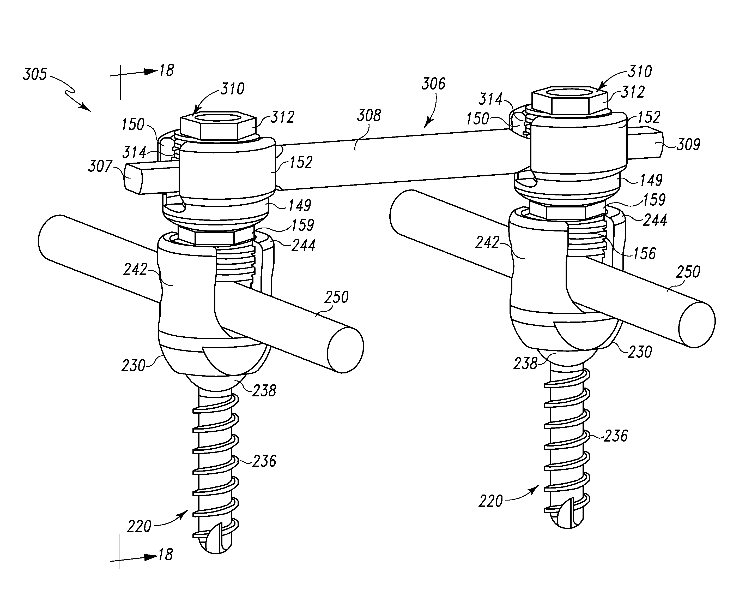
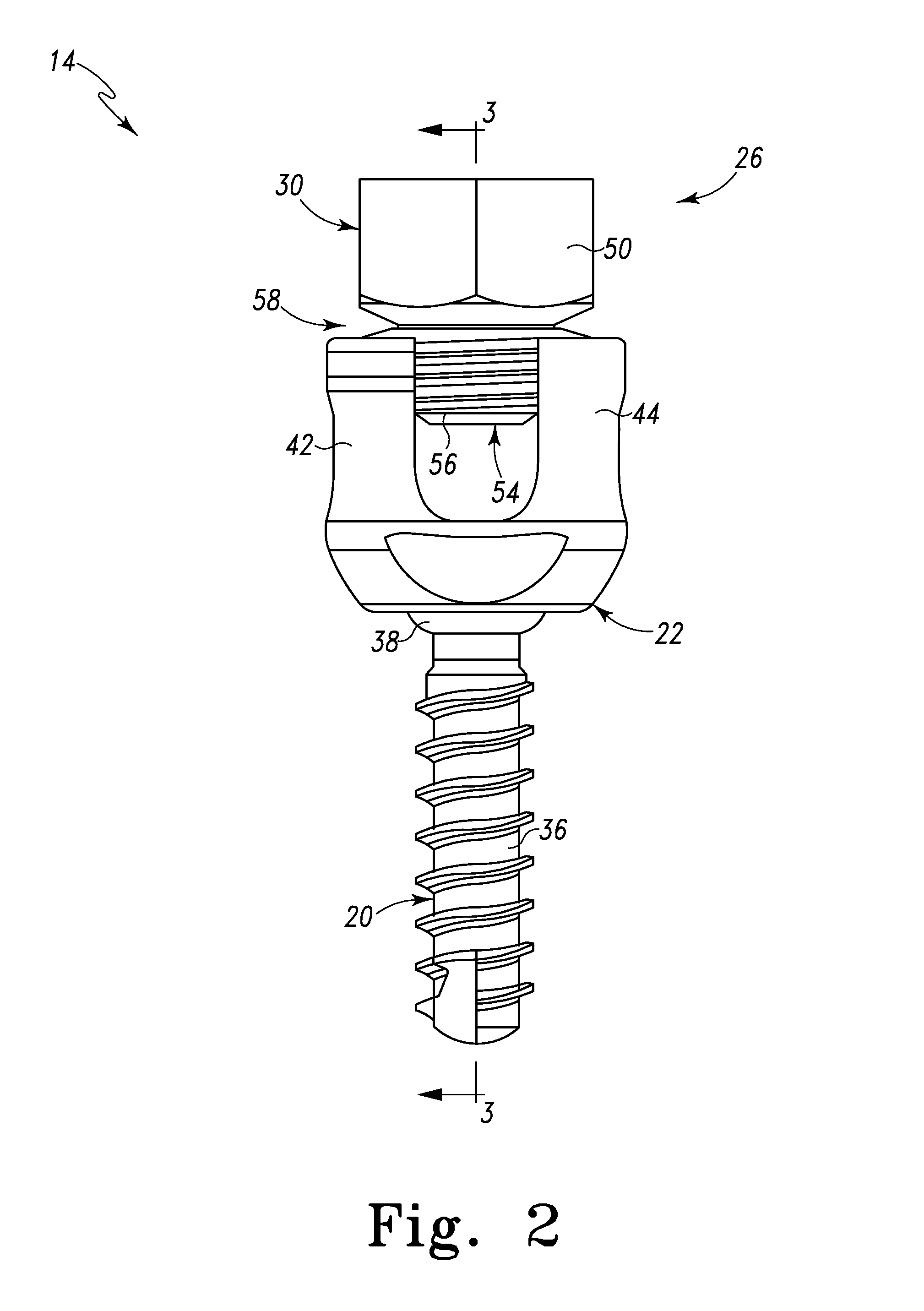
[0012]In one form, the present invention is a spinal cross connector assembly for fixation between existing, adjacent spinal rod assemblies. The spinal cross connector assembly includes first and second spinal cross connector head assemblies each of which is configured for fixation to existing, adjacent spinal rod screw heads and connection with a cross connector rod. Each spinal cross connector rod head assembly has a breakaway collar that, once detached, provides a polyaxial cross connector head. The polyaxial cross connector heads thereby allow for multi-planar placement of the cross connector rod. Fixation of the orientation of the polyaxial cross connector heads is achieved through placement of a set screw in the polyaxial cross connector head.

Problems solved by technology

While current spinal cross connectors are effective, problems exist such as in mounting and maintaining the cross connector in a desired position and orientation with respect to the spinal rods.
Other problems also exist with current cross connectors such as height limitations, sizing, locking and ease of installation issues.

Method used


Image

  • Posterior Cervical Cross Connector Assemblies
  • Posterior Cervical Cross Connector Assemblies
  • Posterior Cervical Cross Connector Assemblies

Examples


Embodiment Construction

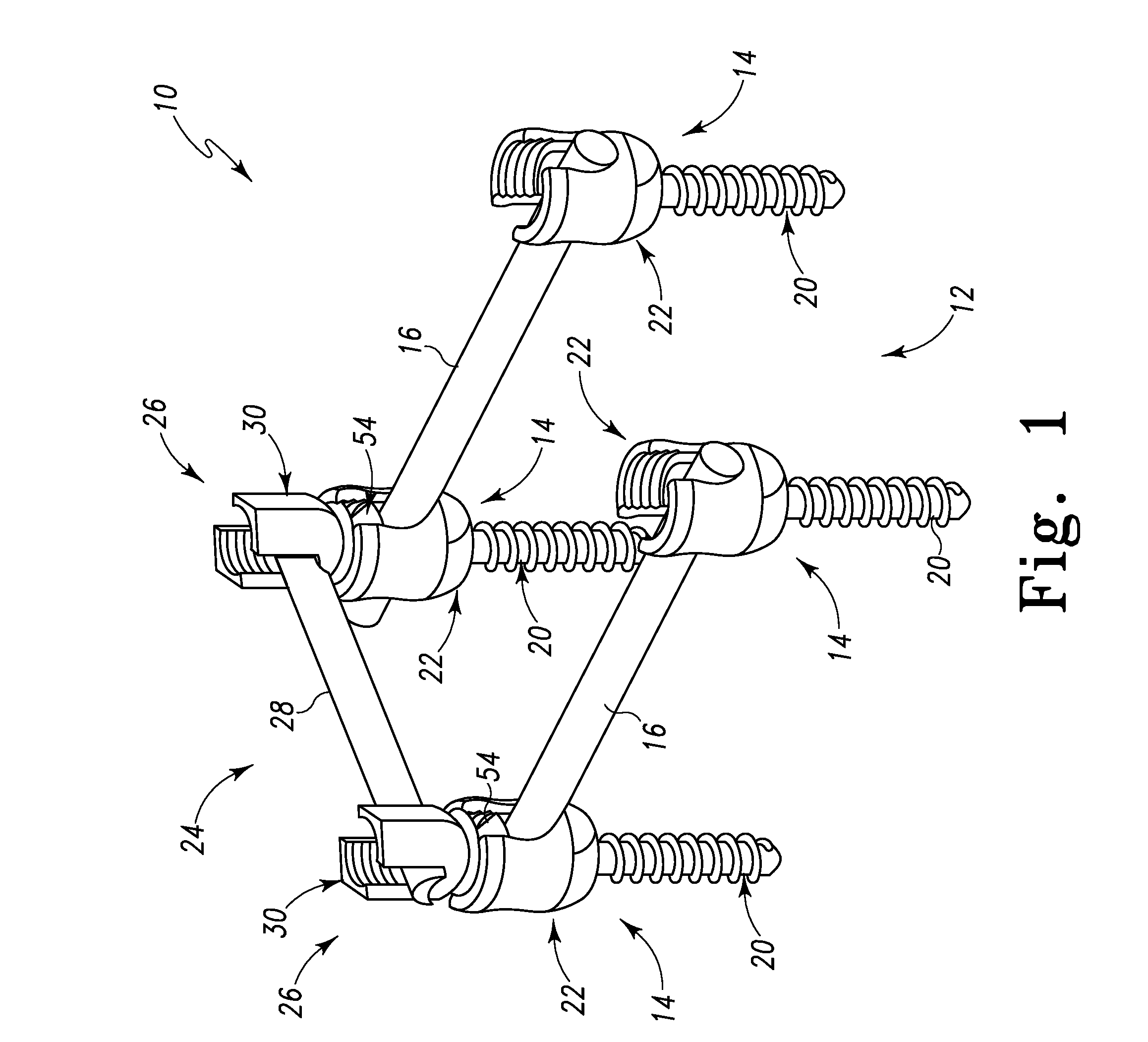
[0038]Referring to FIG. 1, there is depicted a perspective view of a spine fixation construct, generally designated 10, of which would be used in spine stabilization situations. The spine fixation construct 10 shown in FIG. 1 comprises an existing spine stabilization system, generally designated 12, and a cross connector assembly 24 and its accompanying components as described herein, according to the present principles, affixed to the existing spine stabilization system 12. The cross connector assembly 24 and is accompanying components are made from a biocompatible material such as titanium or stainless steel. However, other biocompatible material, materials and / or compounds may be employed.

[0039]The existing spine stabilization system 12 is shown as a single level construct that is configured to attach to and span two adjacent vertebrae (not shown) and consists of two, adjacent spine rod assemblies. Each spine rod assembly has two bone screw assemblies 14 and a spine rod 16. Each ...


PUM


Abstract

A spinal cross connector head assembly and a cross connector assembly utilizing the spinal cross connector head assembly are configured for fixation to an existing spinal rod bone screw head. The spinal cross connector head assembly has one or more components which incorporate one or more breakaway portions that aid in the installation of the cross connector head assembly onto a polyaxial spinal rod bone screw assembly. The spinal cross connector assembly includes first and second spinal cross connector head assemblies each of which is configured for fixation to existing, adjacent spinal rod screw heads and connection with a cross connector rod. Each spinal cross connector rod head assembly has a dual breakaway system including a cross connector head component having a breakaway collar that, once detached, provides a polyaxial cross connector head, and a set screw component having a breakaway set screw that, once detached, provides fixation of the orientation of the polyaxial cross connector head relative to the polyaxial spinal rod bone screw head.

Description

RELATED APPLICATIONS[0001]This patent application claims the benefit of and / or priority to U.S. Provisional Patent Application Ser. No. 61 / 139,737 filed Dec. 22, 2008, entitled “Posterior Cervical Cross Connector Assembly” the entire contents of which is specifically incorporated herein by this reference.BACKGROUND OF THE INVENTION[0002]1. Field of the Invention[0003]The present invention relates to relates to spinal fixation devices that are attached onto a patient's spine such as spinal rods and spinal rod screws (spinal rod assemblies) and, more particularly, to spinal cross connectors for attachment to adjacent spinal rod assemblies.[0004]2. Background Information[0005]There are many medical situations such as disease, injury, trauma or deformity, where it is necessary to align, hold, maintain and / or fix a desired relationship between adjacent vertebrae of the spine. In order to accomplish this goal, orthopedic spinal surgeons utilize spine fixation devices that are attachable t...

Claims


Application Information

Patent Timeline
Patent Type & Authority Applications(United States)
IPC IPC(8): A61B17/86
CPCA61B17/705A61B17/7037A61B17/7049
Inventor BUTLER, MICHAEL S.PREDICK, DANIEL
Owner LIFE SPINE INC
Learn More