Liquid Level Monitoring Apparatus and Methods

a technology of liquid level monitoring and monitoring apparatus, which is applied in the direction of level indicators by pressure measurement, liquid/fluent solid measurement, engine lubrication, etc., can solve the problems of inability to continuously monitor the level output device, the power-down state of the sensors per se may go undetected, and the inhomogeneous nature of the medium of the liquid level sensor in practical applications such as waste water management, so as to improve the accuracy and consistency of time overflow, and the effect of easy

Active Publication Date: 2010-07-01
MULTITRODE
View PDF13 Cites 16 Cited by
  • Summary
  • Abstract
  • Description
  • Claims
  • Application Information

AI Technical Summary

Benefits of technology

[0034]In the present invention, the pressure transducer may be used with its reference tube occluded to prevent destruction by ingress of liquid, the signal being processed by a control means that includes an independent atmospheric reference.
[0044]Cable damage through accident and particularly through the action of vermin such as rats is a common cause of failure. Early identification of such damage allows for preventative maintenance to be undertaken before monitoring apparatus failure.
[0049]More than one frequency may be used. Vibrator may be activated immediately on sensing of discrepancies between probe and pressure sensor readings. This combined with the two methods of analogue and probe level detection working in harmony, will, under the present and increasing strict EPA regulations, provide municipalities and industry a real solution to a real and increasing problem.
[0058]The controller programming capability may include the ability to select a variety of preset and configurable control algorithms to optimise station performance and reliability.
[0065]The controller may preference the bottom probe sensor to ensure pumps are turned off in the area where analogue is unreliable due to low heads, turbulence and liquid density variations due to suspended air etc. The use of a controller as above will use the best of both systems over each zone to continually calculate inflow, volume pumped, pump and station flow rates, time to overflow much more accurately and consistently than previously.
[0067]Currently, most operators use the visual method of selecting the appropriate sensor for pump starts, stops, low and high alarms. This is due to the fact that analogue settings not user friendly. For instance, the second pump start point may need to be just below the inflow in the pit which may be several meters from the top opening. To set an analogue setpoint at this point will require the operator to wait (for a long time) for the station to fill up to this point as to measure from the bottom up and convert to a 4-20 mA point is difficult. The operator will now be able to easily see the sensors on the probe and can select level set points accordingly. This will also set the “invisible” analogue set point simultaneously.

Problems solved by technology

An inherent difficulty which occurs with liquid level sensors in practical applications such as waste water management lies in the inhomogeneous nature of the medium in which they operate.
The monitoring apparatus provides reliable sensing at each sensor station along the body, but is not a continuous analogue level output device by virtue of the sensors being spaced along the body.
The liquid level above the topmost sensor and below the bottommost sensor is also not detected or monitored by the device, which also means that a power-down state of the sensors per se may go undetected.
This approach has been unsuccessful due to the difficulty in reliably installing a pressure sensor low enough in a sewerage well to be effective.
Although the probe operates well at a low liquid cut off level, the pressure transducers are unreliable at this low liquid level.
Turbulence is extreme at the last stages of pump out which effects liquid density so that presently available pressure sensors cannot be used at this low level.
The pressure sensor obviously cannot be used at the lower (pump cut-off) level since the signal disappears into noise as the head pressure approaches zero.
However, complete pump out of the well cannot be achieved accurately due to the inability to accurately calibrate the sensor in the highly variable environment.
A higher cut off level does not evacuate the pit of liquid effectively, thereby resulting in excessive fat and debris build up due to it floating and concentrating in the top layer of liquid.
Arbitration techniques including a redundant low-level cutout sensor installed independently are known, and can result in pumps not being turned off at the appropriate time resulting in pump damage.
In addition, an installation may have hundreds of sites so variables including sensing distances of analogue probe sensors, different models and lengths of probes, and changeable set points for pump starts / stops make the option to install independent systems unviable.
It is very difficult to physically to reliably install a separate pressure transducer at a consistent fixed distance say 60 mm lower than the bottom sensor of the probe.
In any case, both the probe and sensor need to be removed for cleaning on a regular basis so there will be a difference in levels due to reinstallation and also stretching of the sensor's cable or movement due to turbulence affects the position of the pressure transducer.
Also, when the pump station is reaching the low pump out level, turbulence and water action can be extreme, so a separate pressure sensor unit will be violently washed around and damaged by the turbulence.
Currently, pressure transducers are mounted much higher than the optimum level to try to overcome problems and damage due to turbulence but, even so, many transducers are still damaged from turbulence and extreme water flows found in sewerage pumping stations.
Fixing a separate pressure sensor to or near the probe, seriously affects the operation and reliability of the probe as excessive build up gets trapped between the sensor cable and probe.
The duty point on the probe is a problem because this is where build up occurs which may eventually cause the probe to fail.
However, the previously described calibration problem remains.
Because high level alarms are rare, probe sensors and connections are not confirmed regularly.
Currently, once level is beyond the top of the probe, no more monitoring is available.
Currently, deploying dual back up systems of any kind is problematic.
Dual back up systems are very difficult to commission and are subject to continual operational changes, which result in unreliability, false trips and system failure, mainly due to arbitration to which is the correct reading.
During arbitration in systems including two independent level sensors, it is difficult to determine which sensor reading is correct in the event that there is a discrepancy between sensor readings.

Method used


Image

  • Liquid Level Monitoring Apparatus and Methods
  • Liquid Level Monitoring Apparatus and Methods
  • Liquid Level Monitoring Apparatus and Methods

Examples


Embodiment Construction

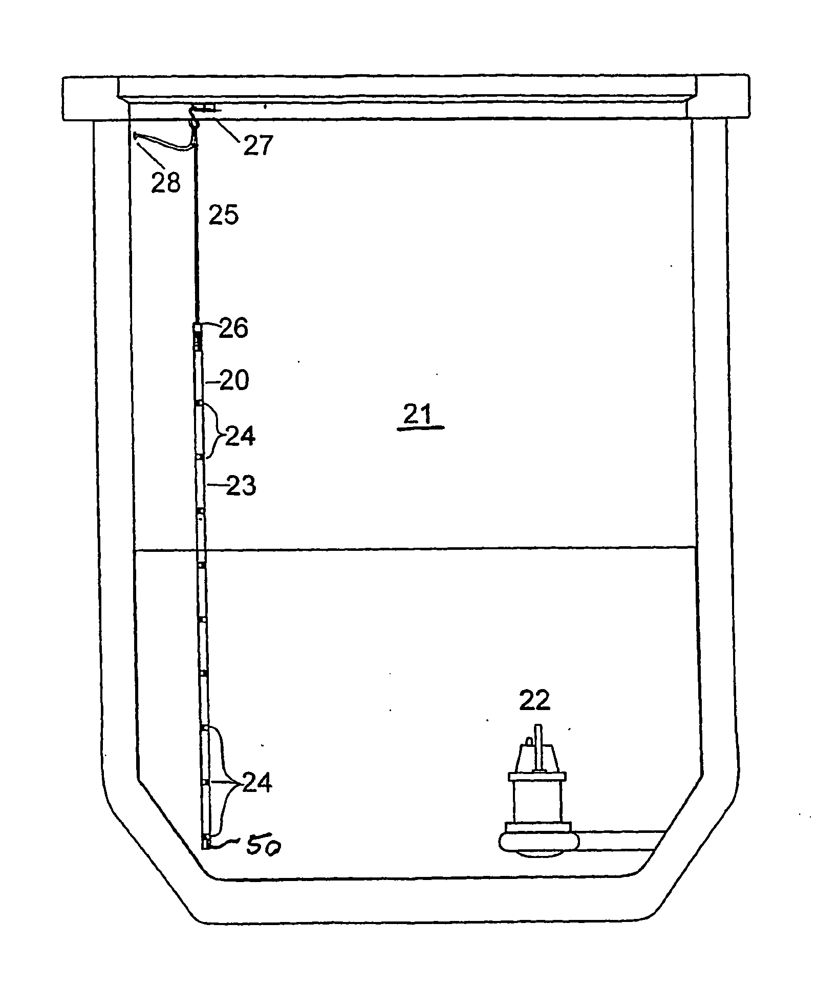
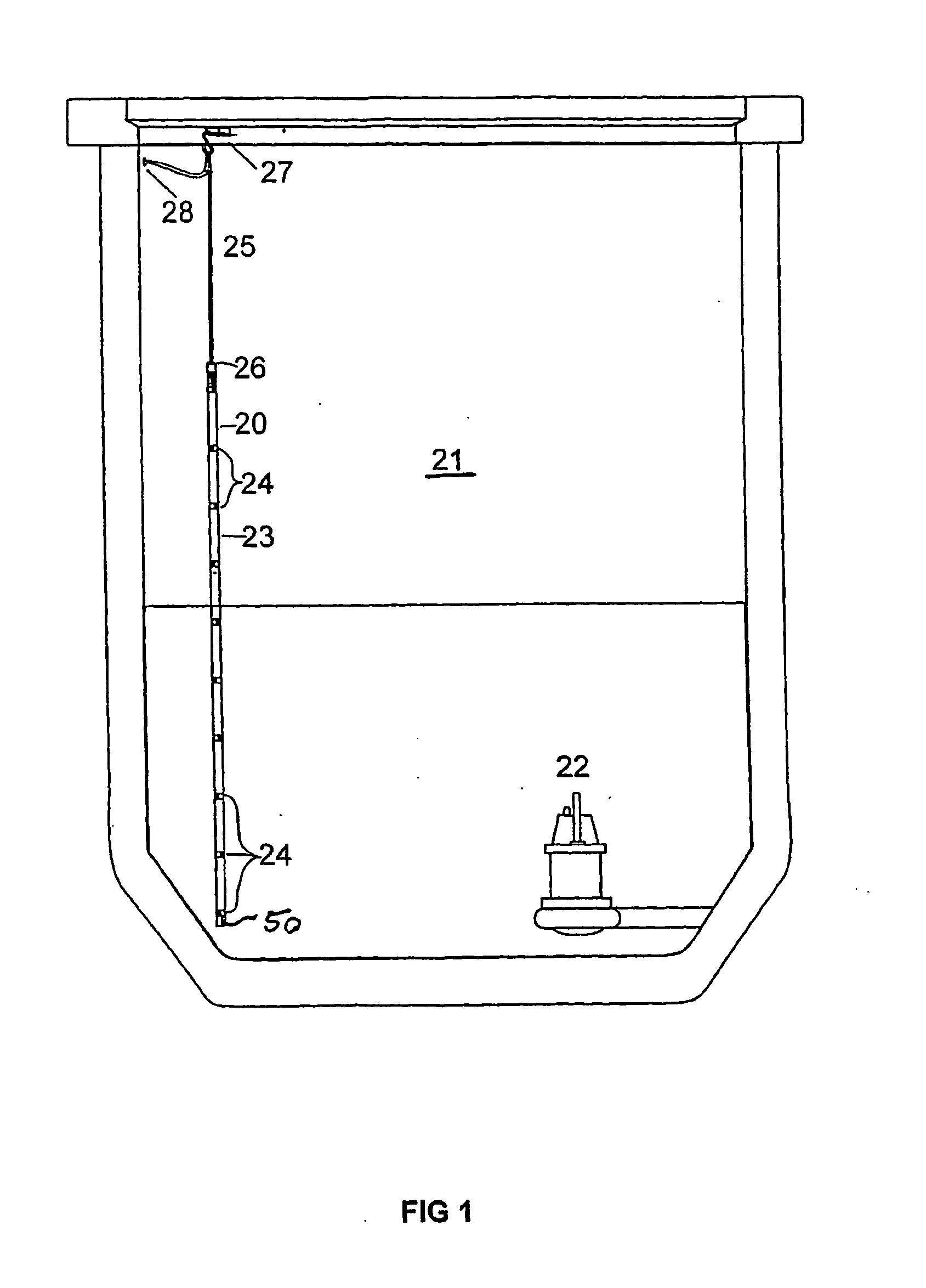
[0084]Referring to FIG. 1 it will be seen that the monitoring assembly 20 may be installed in a sewage pit 21 in which a submersible pump assembly 22 is installed for maintaining the sewage at a desired level. For this purpose the monitoring assembly 20 includes an elongate body 23 formed of plastics material and supporting a plurality of sensors 24 in 10 vertically spaced apart relationship such that the sensors 24 are electrically isolated from one another. In the monitoring assembly 20 in the illustrated embodiments there are provided ten sensors 24. The sensor spacing can be equidistant or spaced at variable lengths. The body 23 may have a diameter of 30 millimetres but of course these dimensions can be varied as desired. Each sensor means 24 is dual-connected to a respective lead of a pair of multi-core cables 25 which are secured sealably to the top end 26 of the monitoring assembly. The cables 25 are supported by an upper mounting 27 adjacent the entrance to the pit 21 and fr...


PUM


Abstract

The present invention relates to a liquid sensor for locating in a liquid. The liquid sensor includes a level sensor including one or more sensing stations located between a head and a tail of the liquid sensor. The liquid sensor is suitable for sensing the liquid level. The liquid sensor further includes a depth sensor for sensing the depth of the tail in the liquid. The liquid sensor is particularly suited to pumping station applications.

Description

TECHNICAL FIELD[0001]This invention relates to liquid level monitoring apparatus and methods.[0002]This invention has particular but not exclusive application to liquid level monitoring apparatus and methods for water and waste water management, and for illustrative purposes reference will be made to such application. However, it is to be understood that this invention could be used in other applications, such as aqueous and non-aqueous liquid level monitoring apparatus and methods generally.BACKGROUND TO THE INVENTION[0003]The reference to any prior art in this specification is not, and should not be taken as an acknowledgement or any form of suggestion that the prior art forms part of the common general knowledge.[0004]U.S. Pat. No. 4,739,786 and its related publications derived from WO86 / 02725 describe a monitoring assembly which has a plurality of sensors arranged in spaced relationship along a body which may be suspended from a coded multicore cable in a reservoir to monitor li...

Claims


Application Information

Patent Timeline
Patent Type & Authority Applications(United States)
IPC IPC(8): G01F23/14G01F23/28
CPCG01F23/185G01F23/242G01F23/241G01F23/0007G01F23/24G01F25/0061G01F25/20
Inventor PARKINSON, CRAIG STEPHEN
Owner MULTITRODE
Why Eureka
Try Eureka