
Method for Producing Hot Water Utilizing Combined Heat Resources of Solar Energy and Heat Pump in the Manner of Heating Water at Multilpe Stages and Accumulating Energy and a Device Especially for Carrying Out the Method

a technology of solar energy and heat pump, which is applied in the field of solar energy, can solve the problems of low solar radiant energy, low energy-flux density, and inability to meet the needs of the user, and achieve the effect of improving the efficiency of the collector, facilitating the use of off-peak electricity, and facilitating the collection

Inactive Publication Date: 2010-07-01
PAN
View PDF30 Cites 35 Cited by
  • Summary
  • Abstract
  • Description
  • Claims
  • Application Information

AI Technical Summary

Benefits of technology

"The present invention provides a method for producing hot water using combined heat resources of solar energy and heat pumps in a timesharing mode. The method involves heating water at multiple stages and accumulating energy in a water tank for supplying hot water in a timesharing mode. The invention solves the problem of limited solar energy availability by setting a highest priority for utilizing solar energy and off-peak electricity. The device for carrying out the method includes a solar energy collector, heat pumps, electrical heaters, water tanks, and control unit. The method and device provide efficient and cost-effective production of hot water."

Problems solved by technology

The radiant energy reaching the earth's surface from the sun each year equals to the energy generated by about 130 trillion tons of standard coals, but it is still dispersal, discontinuous, and unstable.
Although the total amount of solar radiant energy reaching the earth's surface is great, its energy-flux density is very low.
The discontinuance and instability means that the solar radiant energy is restricted by natural conditions such as days and nights, seasons, geographical latitudes, altitudes above sea level, as well as random factors such as clear, gloomy, cloudy, and rainy days.
The energy used for building, such as for producing hot water, can be generated by low-ordered renewable energy sources; otherwise, it would be a waste of power if the high-ordered electric energy is used.
Since the cold water will be input at any time, it is impossible to supply a certain amount of hot water above 45° C. for 24 hours a day and 365 days a year if a non-heat storage water tank of a normal size is used.
Moreover, in sunny days, as the temperature at the upper part of the heat storage water tank gradually goes up, the energy collecting efficiency of the solar energy collecting system declines gradually from noon.
Therefore, the overall thermal performance of the system is quite low.
If the energy is accumulated by means of enlarging the volume of the heat storage water tank, the water in the lower part always has a low temperature, which does not make sufficient contributions for the everyday output of hot water.
Besides, the water at a lower temperature gets bacteria more easily, and gets the supplied water being polluted.
Furthermore, the hot water can be easily mixed with the cold water if no separation and heat preservation technique is used, so the water in the upper part of the tank does not easily reach the required output temperature, and the water tank is too large to be fully utilized.
In addition, the hot water chamber and the cold water chamber are arranged independently for seasonal use, which reduces the application rate greatly, but increases the arranging fee.
However, the efficiency of the electric heat pump is limited by the required temperature and the temperature range of the hot source, and it will be frosted below the critical temperature.
If the temperature difference in heating is too large, it will be easily damaged.
Moreover, it's preferred to use off-peak electricity to produce hot water with the electric heat pump, as the electrical power is in shortage.
However, the water-heating device in this technical solution still has some problems, for example, the solar energy cannot be fully utilized when the area for installing the solar energy collector is limited, and meanwhile, the heat pump must be used to make up the insufficient part where the solar energy is insufficient.
However, it is difficult to get sufficient off-peak electricity at night for family users whose lead-in current capacity is fixed.
Meanwhile, the water tank must be relatively large to realize the effects of accumulating the energy and reducing the cost, which increases the arranging fee for the water-heating device.
For a large-scale concentrated water-heating device, enlarging the volume of the water tank not only increases the arranging fee, but also brings the problems of mounting on the roof and support capacity of the mounting surface.
Moreover, the area for mounting the solar energy collector is reduced, so the adaptation of mounting is affected.

Method used


Image

  • Method for Producing Hot Water Utilizing Combined Heat Resources of Solar Energy and Heat Pump in the Manner of Heating Water at Multilpe Stages and Accumulating Energy and a Device Especially for Carrying Out the Method
  • Method for Producing Hot Water Utilizing Combined Heat Resources of Solar Energy and Heat Pump in the Manner of Heating Water at Multilpe Stages and Accumulating Energy and a Device Especially for Carrying Out the Method
  • Method for Producing Hot Water Utilizing Combined Heat Resources of Solar Energy and Heat Pump in the Manner of Heating Water at Multilpe Stages and Accumulating Energy and a Device Especially for Carrying Out the Method

Examples


first embodiment

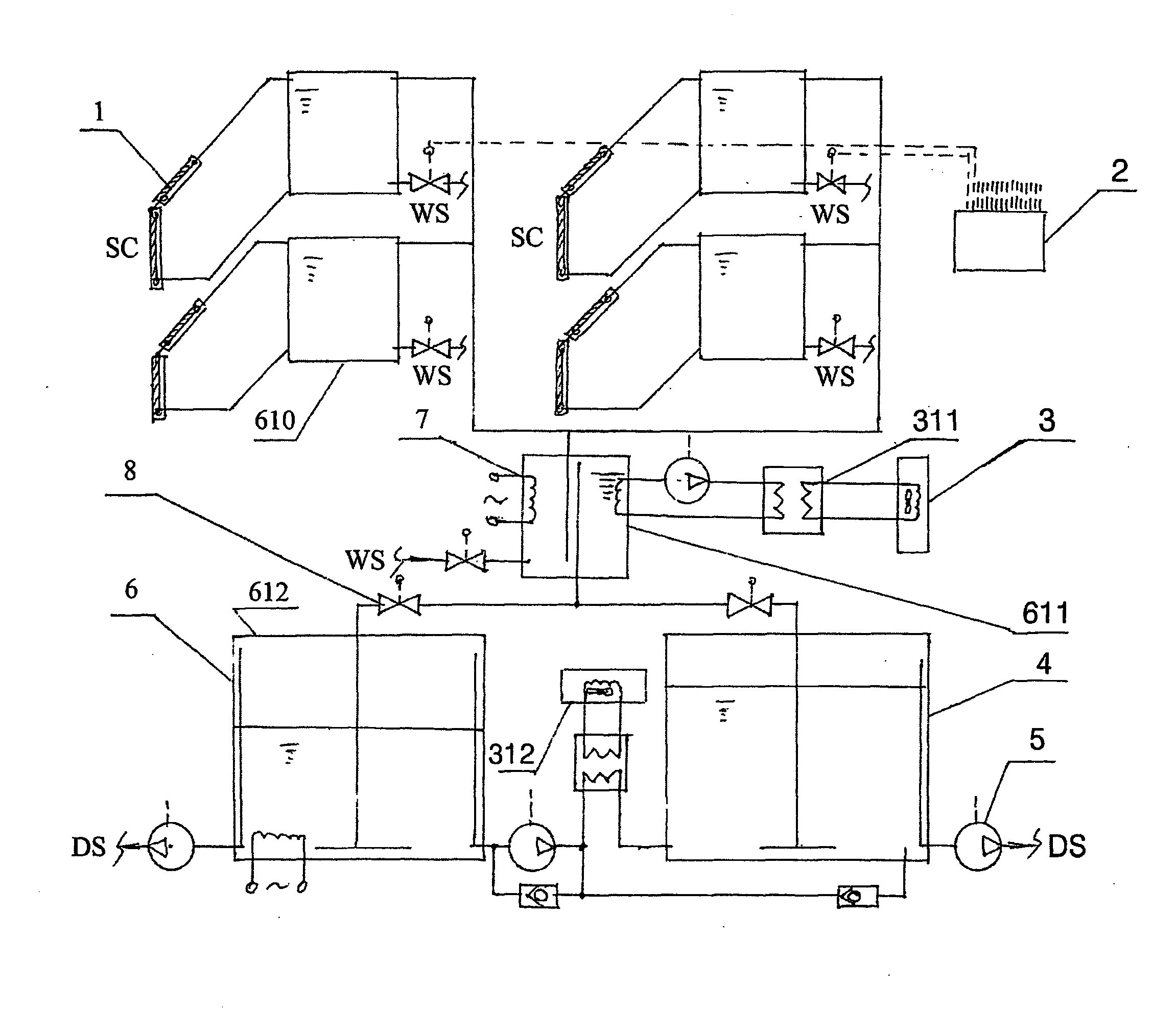
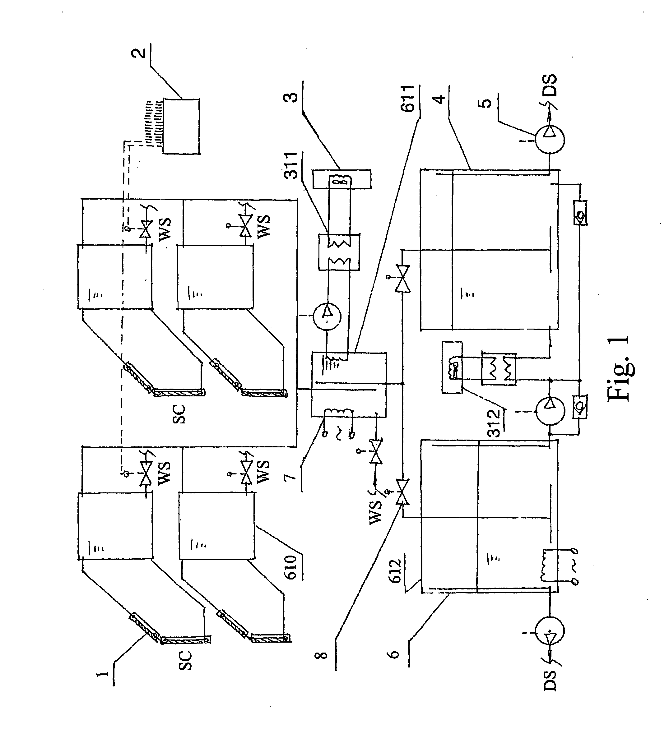
[0024]FIG. 1 is a schematic structural view of a device according to the present invention, which includes at least one solar energy collector 1, a control unit 2, at least one heat pump 3, at least one water tank 4, at least one booster pump 5, at least one water-heating tank 6, at least one electrical heater 7, and at least one electric control valve 8.

[0025]The water-heating tank 6 is a water tank for heating at multiple stages formed by two or more multi-stage heating water tanks 611 and 612. The multi-stage heating water tank 611 is a conflux hot water tank of multi-stage heating, and the multi-stage heating water tank 612 is a warm water storage tank of multi-stage heating. The multi-stage heating water tank 611 includes circulating water-heating tank for the collector of multi-stage heating 610 and the conflux hot water tank of multi-stage heating 611. The hot water tanks of multi-stage heating 611 and 612 are mounted in front of the final temperature water storage tank 4. Th...

second embodiment

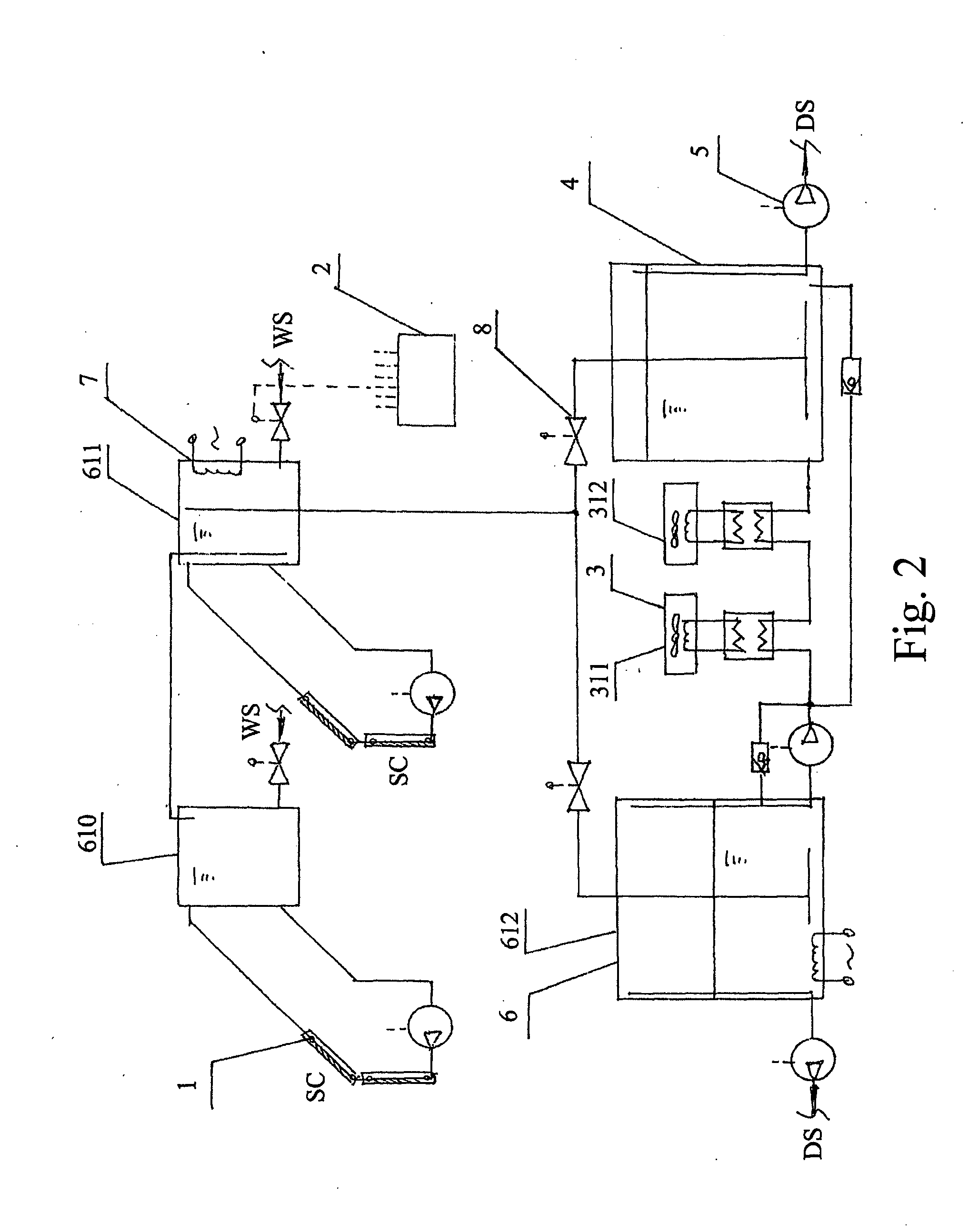
[0033]FIG. 2 is a schematic structural view of a device according to the present invention, which includes at least one solar energy collector 1, a control unit 2, at least one heat pump 3, a final temperature water storage tank 4, a booster pump 5, at least one water-heating tank 6, at least one electrical heating element 7, and at least one electric control valve 8. In FIG. 2, multi-stage heating units of different temperatures are formed between the solar energy collector 1 and the heat pump 3, and meanwhile, two multi-stage heating outputs formed by the multi-stage heating units of the solar energy collector are connected to corresponding multi-stage heating water tanks 610 and 611 via pipelines.

[0034]The multi-stage heating water tank includes the electrical heating element 7. The multi-stage heating outputs formed by the multi-stage heating units of different temperatures constituted by the solar energy collector and the heat pump are connected to the corresponding multi-stage...

third embodiment

[0039]FIG. 3 is a schematic structural view of a device according to the present invention, which includes a solar energy collector 1, a control element 2, at least one heat pump 3, a final temperature water storage tank 4, a booster pump 5, at least one heating water tank 6, and at least one electrical heating element 7. In FIG. 3, the solar energy collector 1 and the heat pump 3 can form multi-stage heating units of different temperatures. The multi-stage heating outputs formed by the multi-stage heating units for the solar energy collector and the heat pump are connected to corresponding multi-stage heating water tank 6 via pipelines. The multi-stage heating water tank can include an electrical heating element 7. The solar energy collector, the water tank, the water pump, the water-heating tank, the heat pump, and the electrical heater are electrically connected to the control unit 2 respectively. A predetermined amount of produced hot water is heated at multiple stages and be se...


PUM


Abstract

A method for producing hot water and a device especially for carrying out the method are provided. The method utilizes combined heat resources of solar energy and heat pump in the manner of heating water at multiple stages and accumulating energy. The device comprises solar energy collector, heat pump, electrical heater, water tank, and control unit. The device also includes water-heating tanks with multiple stages. A heating means with multiple stages at different temperatures is formed either by the solar energy collector or by the collector and the heat pump. The outputting end of the two or more heating stages constituted by the solar energy collector or by the collector and the heat pump is connected through ducts to the corresponding water-heating tanks. A predetermined amount of produced water heated at multiple stages is respectively stored in the water-heating tanks. Compared with the prior art, the present invention is endowed with the performance of making use of the solar energy to the greatest extent and utilizing off-peak electricity more efficiently as a supplementary heating means. Furthermore, the arranging fee of the device is reduced and its adaptation of mounting is improved.

Description

FIELD OF THE INVENTION[0001]The present invention relates to a field of utilizing solar energy, and more particularly to a method for producing hot water utilizing combined heat resources of solar energy and heat pump in a manner of heating water at multiple stages and accumulating energy and a device especially for carrying out the method.BACKGROUND OF THE INVENTION[0002]The sun generates a large amount of energy. The radiant energy reaching the earth's surface from the sun each year equals to the energy generated by about 130 trillion tons of standard coals, but it is still dispersal, discontinuous, and unstable. Although the total amount of solar radiant energy reaching the earth's surface is great, its energy-flux density is very low. So a large area is needed to receive the radiation in order to get a certain radiant power. The discontinuance and instability means that the solar radiant energy is restricted by natural conditions such as days and nights, seasons, geographical la...

Claims


Application Information

Patent Timeline
Patent Type & Authority Applications(United States)
IPC IPC(8): F24J2/42F24J2/00F24J2/04F24S90/00
CPCF24D11/0221Y02B10/70Y02B10/20Y02E10/50F24D11/02F24H1/18H02S10/00
Inventor PAN
Owner PAN
Learn More