Plasma processing apparatus

a processing apparatus and plasma technology, applied in the direction of electrical apparatus, electric discharge tubes, basic electric elements, etc., can solve the problem of non-uniform gas supply amount, and achieve the effect of uniform processing rate and sample processing shap

Inactive Publication Date: 2010-07-01
HITACHI HIGH-TECH CORP
View PDF15 Cites 113 Cited by
  • Summary
  • Abstract
  • Description
  • Claims
  • Application Information

AI Technical Summary

Benefits of technology

[0022]According to the invention, a uniformed gas supply distribution is given to the entire surface of the sample without making the apparatus

Problems solved by technology

Particularly, in the case of a narrow-gap type apparatus, there sometimes arises a problem to occur a non-

Method used


Image

  • Plasma processing apparatus
  • Plasma processing apparatus
  • Plasma processing apparatus

Examples


embodiment 1

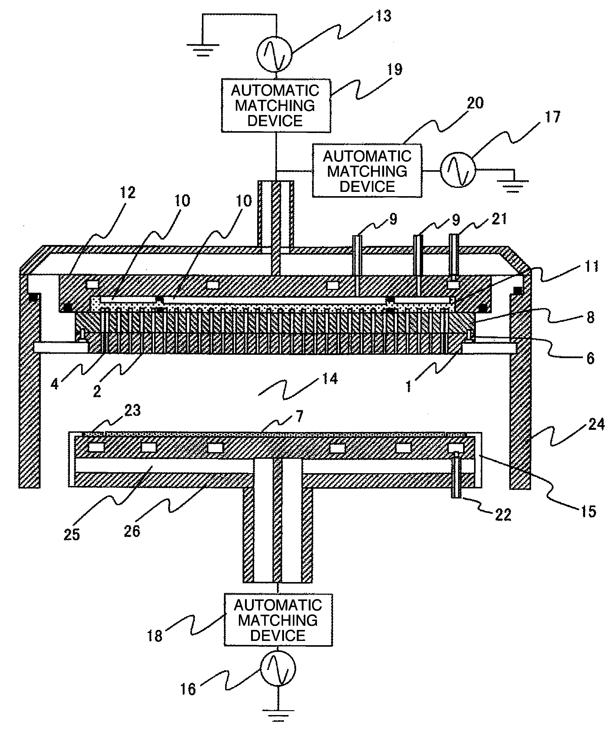
[0040]A first embodiment of the invention will be described with use of FIG. 1 and FIG. 2.

[0041]FIG. 1 is shows a section view of a plasma processing apparatus in one embodiment of the invention. The plasma processing apparatus includes an electrostatic chucking function built-in electrode (sample table) 15 for placing a sample 7 in a vacuum chamber 24 and a shower plate (gas supply unit) 1 faced to the sample table 15. In this way, a 200 MHz high-frequency power is supplied from a discharge-use high-frequency power source 13 to a conductor-type antenna 12 incorporated with a plate 8 and a dispersion plate 11 to turn a gas supplied from the shower plate 1 into a plasma in a discharge space 14. Further, a 4 MHz high-frequency voltage is applied to the sample 7 from a high-frequency power source 16 via the electrostatic chucking function built-in electrode 15 to accelerate ions in the plasma and to be incident to the surface of the sample 7. The 4 MHz high-frequency voltage is also ap...

embodiment 2

[0073]A second embodiment of the invention will be described with use of FIG. 15.

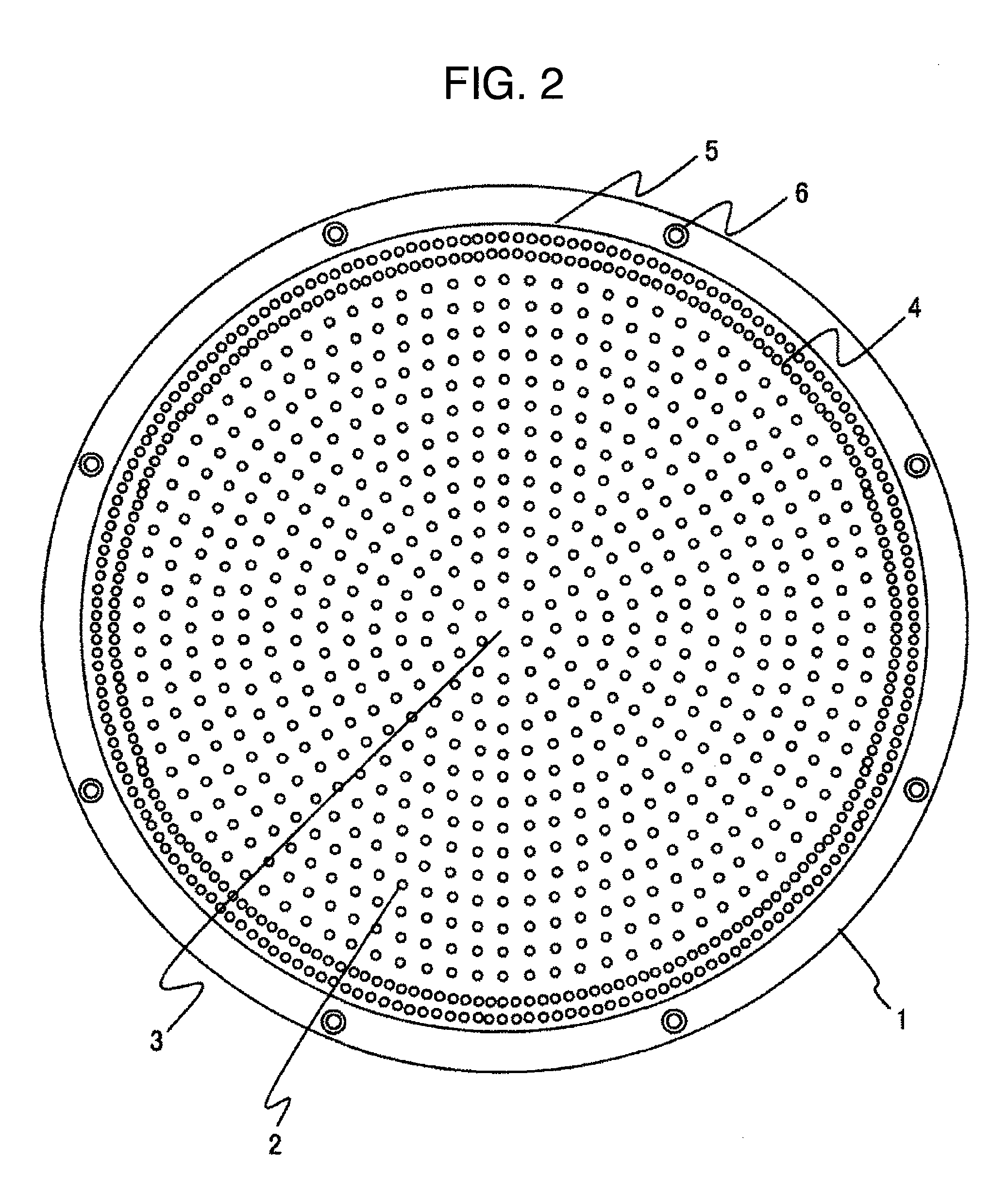
[0074]FIG. 15 is a schematic diagram showing a shower plate 1 in the second embodiment of the invention.

[0075]In the case of this embodiment, each diameter of gas injection holes 27 faced to the wafer edge portion and formed on the periphery portion of the shower plate 1 is 1.3 times that of the other gas injection holes 2, that is, the hole diameter at the periphery portion is 0.65 mm while the other hole diameter is set to 0.5 mm, and the gas-injection-hole number density is set to uniformity. In the case of the first embodiment, the gas supply amount to the wafer edge portion is adjusted by the gas-injection-hole number density of the gas injection holes 4 each having the same diameter and formed at the periphery portion of the shower plate 1. In the case of the second embodiment, the gas supply amount is adjusted by the hole diameter.

[0076]A conductance at a time when the gas passes through the gas ...


PUM

PropertyMeasurementUnit
Diameteraaaaaaaaaa
Densityaaaaaaaaaa
Aspect ratioaaaaaaaaaa

Abstract

A plasma processing apparatus includes a vacuum chamber, a sample table that places the sample in the vacuum chamber, and a gas supply unit faced to the sample table and having a gas supply surface with a diameter larger than that of the sample, wherein gas injection holes each having identical diameter are provided concentrically on the gas supply surface, a hole number density of the gas injection holes present in an outer diameter position of the sample or in an outside of the outer diameter position is made higher than that of the gas injection holes present inside the outer diameter position of the sample, and a diameter of the gas injection holes present in the outer diameter position of the sample or in the outside from the outer diameter position is larger than that of the gas injection holes present inside the diameter of the sample.

Description

BACKGROUND OF THE INVENTION[0001]The present invention relates to a plasma processing apparatus to manufacture semiconductor devices, and in particularly to a dry etching technique to etch semiconductor materials, such as a silicon, a silicon dioxide film, etc., along a mask pattern shape formed by a resist material etc.[0002]The dry etching is a semiconductor micro-fabrication method in which a processing gas is introduced into a vacuum chamber having a vacuum decompression unit, the processing gas is turned into a plasma by an electromagnetic wave to apply it to a sample to be processed, a surface of the sample other than a mask portion is etched to obtain a desirable shape. A processing uniformity on an in-plane sample is affected by a plasma distribution, a temperature distribution on the in-plane of the sample, a supplied gas composition and flow rate distribution, etc.[0003]Particularly, in the case of a parallel plate type plasma processing apparatus, the processing gas is su...

Claims


Application Information

Patent Timeline
IPC IPC(8): C23F1/08
CPCH01J37/32091H01J37/3244H01L21/67069H01L21/3065
Inventor YOKOGAWA, KENETSUICHINO, TAKAMASAHIROZANE, KAZUYUKIKANEKIYO, TADAMITSU
Owner HITACHI HIGH-TECH CORP
Why Eureka
Try Eureka