Battery controlling apparatus for a vehicle
- Summary
- Abstract
- Description
- Claims
- Application Information
AI Technical Summary
Benefits of technology
Problems solved by technology
Method used
Image

Examples
Embodiment Construction
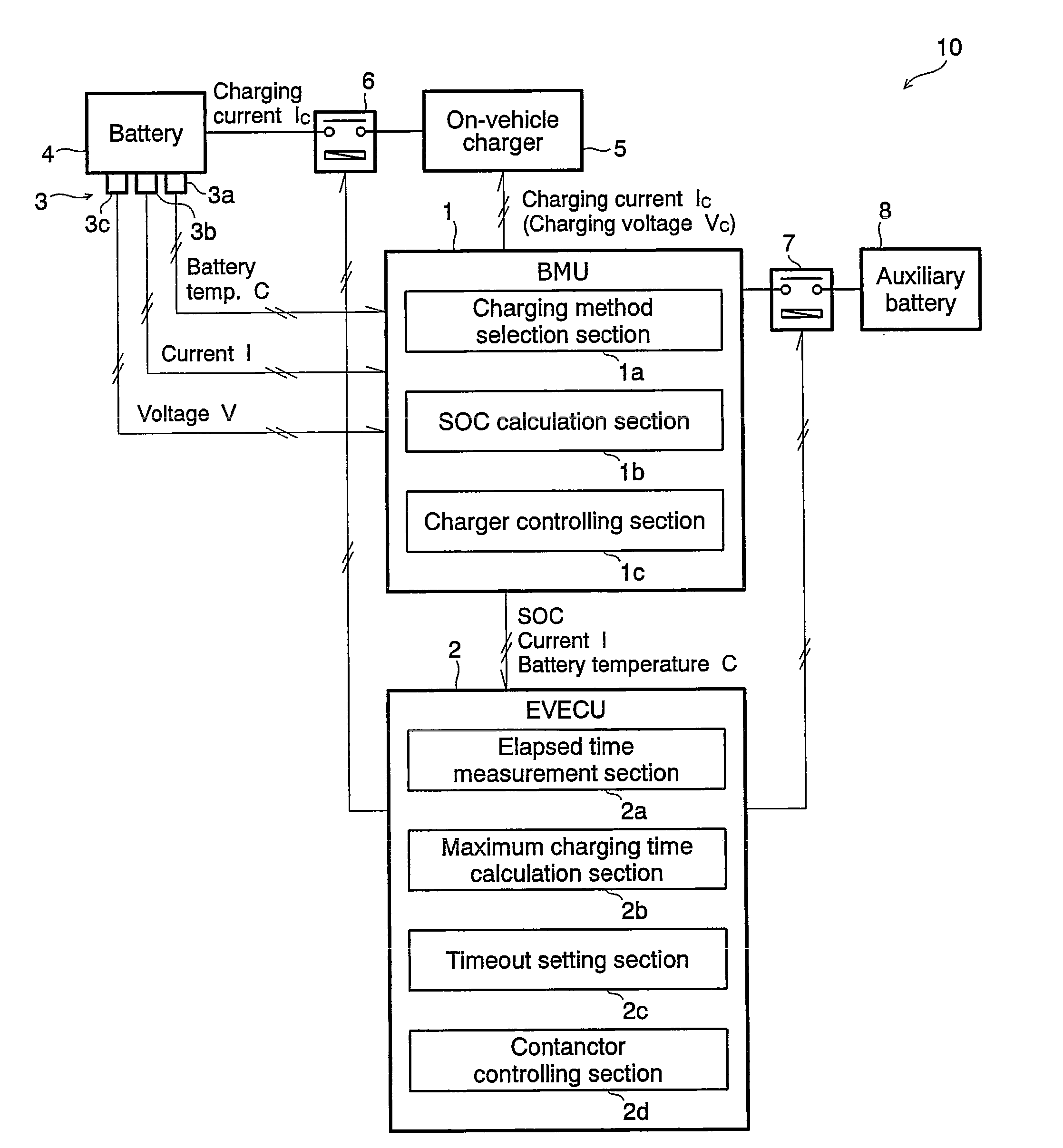
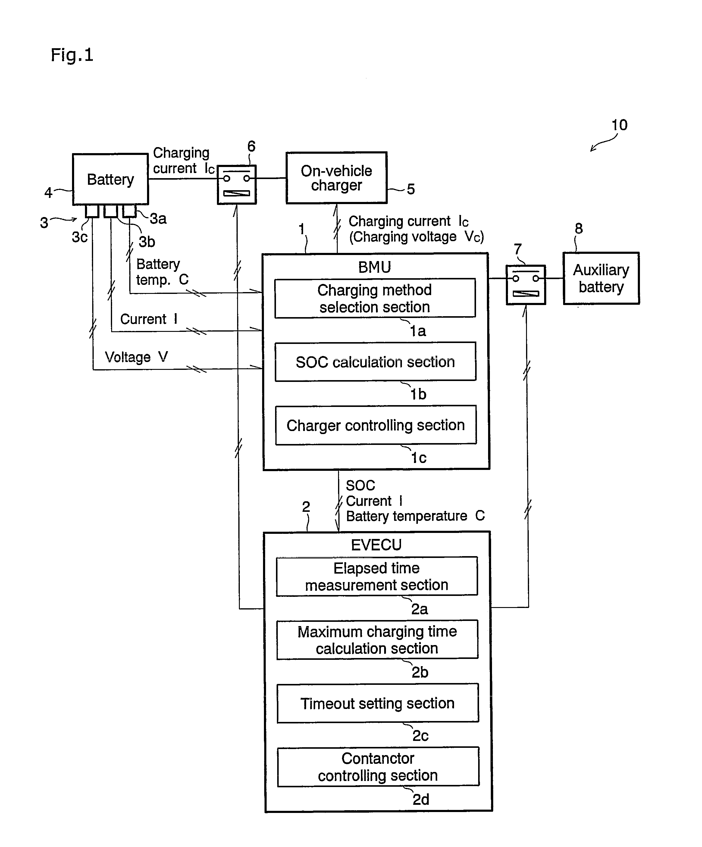
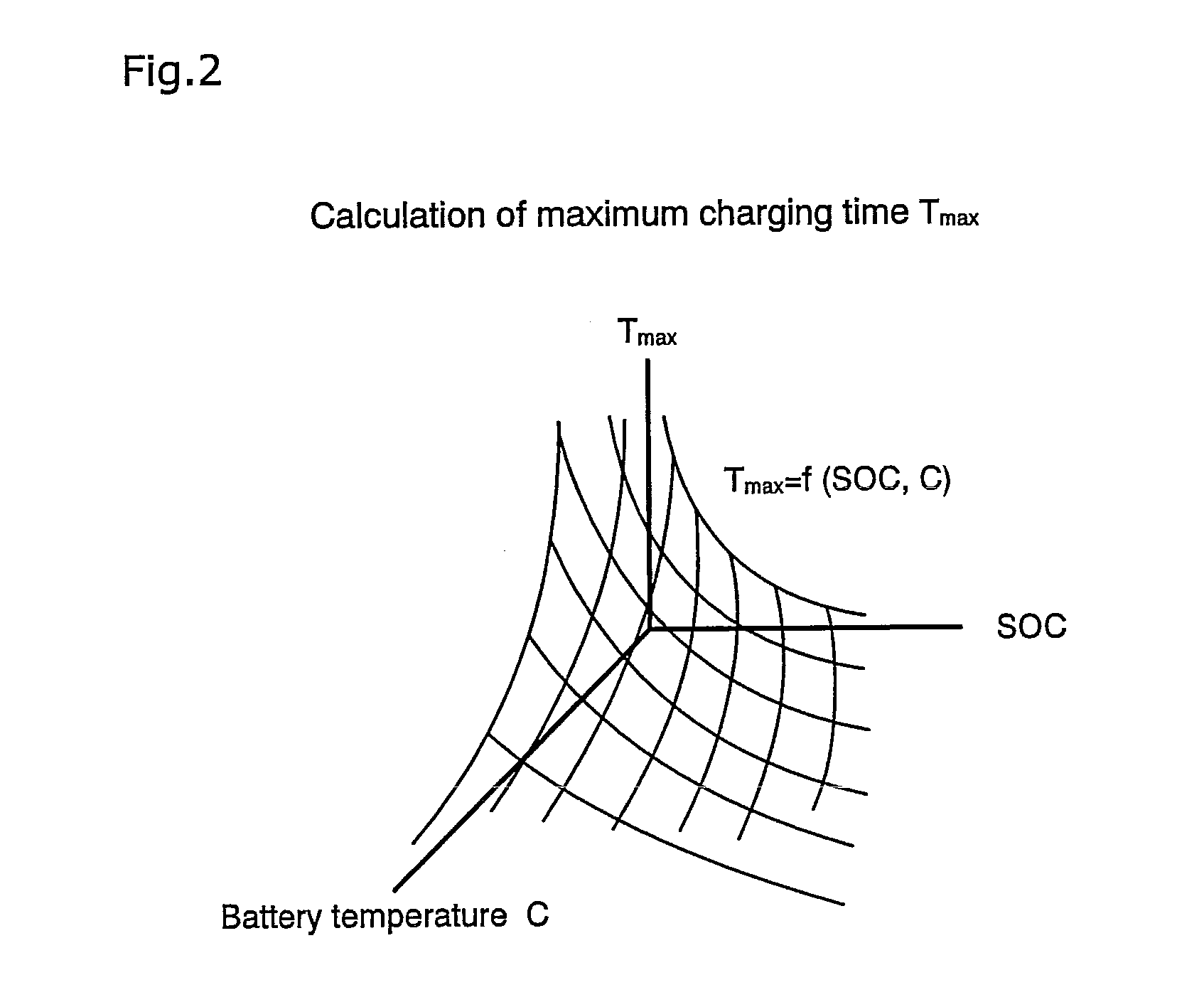
[0049]In the following, an embodiment of the present invention is described with reference to the drawings. FIGS. 1 to 7 are views illustrating a battery controlling apparatus for a vehicle according to an embodiment of the present invention. FIG. 1 is a block diagram showing a general configuration of the battery controlling apparatus. FIG. 2 is a graph illustrating a relationship of maximum charging time to a battery temperature and an SOC in the battery controlling apparatus. FIG. 3 is a graph illustrating a relationship between offset time and current in the battery controlling apparatus. FIG. 4 is a graph illustrating contents of control by the battery controlling apparatus. FIG. 5 is a graph illustrating aged deterioration of the current and the voltage in the charge control by the battery controlling apparatus. FIGS. 6 and 7 are flow charts showing a controlling procedure by the battery controlling apparatus.
[0050][General Configuration]
[0051]The battery controlling apparatus...
PUM
 Abstract
Description
Claims
Application Information
PatSnap Eureka turns technology decisions into work you can execute. Powered by our Innovation Knowledge Graph, it runs expert workflows across engineering, life sciences, materials and intellectual property. Get your review-ready output in minutes.


