Phase mixer and delay locked loop including the same

a phase mixer and delay lock technology, applied in pulse manipulation, pulse technique, instruments, etc., to achieve the effect of preventing increase of jitters

Active Publication Date: 2010-07-01
SK HYNIX INC
View PDF11 Cites 13 Cited by
  • Summary
  • Abstract
  • Description
  • Claims
  • Application Information

AI Technical Summary

Benefits of technology

[0019]Embodiments of the present invention are directed to provide a phase mixer, which is capable of preventing increase of jitters even though PVT is varied, and a delay locked loop including the same.

Problems solved by technology

The above problems may arise in the delay locked loop of FIG. 2 or duty cycle corrector employing the phase mixer 100.

Method used


Image

  • Phase mixer and delay locked loop including the same
  • Phase mixer and delay locked loop including the same
  • Phase mixer and delay locked loop including the same

Examples


Embodiment Construction

[0036]Other objects and advantages of the present invention can be understood by the following description, and become apparent with reference to the embodiments of the present invention.

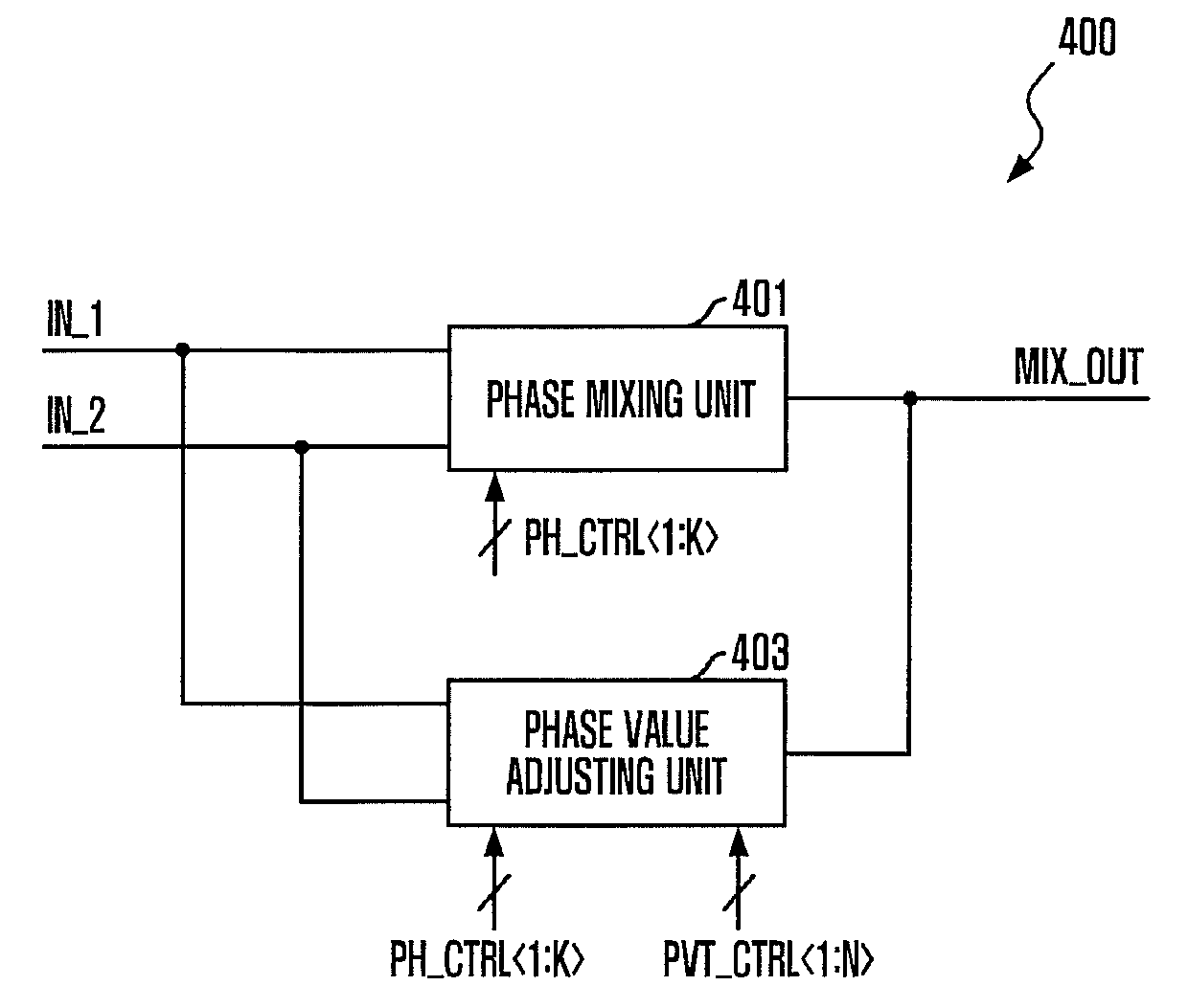
[0037]FIG. 4 is a block diagram of a phase mixer 400 in accordance with an embodiment of the present invention.

[0038]Referring to FIG. 4, the phase mixer 400 includes a phase mixing unit 401 and a phase value adjusting unit 403.

[0039]The phase mixing unit 401 adjusts drive strengths for a first input signal IN_1 and a second input signal IN_2 in response to phase control signals PH_CTRL, and mixes a phase of the first input signal IN_1 and a phase of the second input signal IN_2 to output a phase mixed signal MIX_OUT whose phase is varied by a unit phase value PH_VALUE. The first input signal IN_1 and the second input signal IN_2 may be a first coarse delay clock COARSE_CLK1 and a second coarse delay clock COARSE_CLK2. A phase difference corresponding to a unit delay value UNIT_DD exists between the...


PUM


Abstract

A phase mixer includes a phase mixing unit configured to mix a phase of a first input signal and a phase of a second input signal in response to a phase control signal and output a phase mixed signal whose phase is varied by one or more units of a unit phase value, and a phase value adjusting unit configured to control an operation of the phrase mixing unit so that the unit phase value is adjusted in response to a code signal coding at least one of a process, voltage, or temperature (PVT) variation.

Description

CROSS-REFERENCE TO RELATED APPLICATIONS[0001]The present invention claims priority of Korean patent application number 10-2008-0134635, filed on Dec. 26, 2008, which is incorporated by reference in its entirety.BACKGROUND OF THE INVENTION[0002]The present invention relates to a phase mixer and a delay locked loop including the same, and more particularly, to a phase mixer operating according to PVT variation and a delay locked loop including the same.[0003]FIG. 1 is a circuit diagram of a conventional phase mixer 100.[0004]Referring to FIG. 1, the phase mixer 100 includes first driving units 101 to103 receiving a first input signal IN_1, and second driving units 104 to 106 receiving a second input signal IN_2. The phase mixer 100 mixes a phase of the first input signal IN_1 and a phase of the second input signal IN_2 to output a phase mixed signal MIX_OUT.[0005]The phase mixer 100 mixes the phase of the first input signal IN_1 and the phase of the second input signal IN_2 by driving...

Claims


Application Information

Patent Timeline
Patent Type & Authority Applications(United States)
IPC IPC(8): H03L7/06G06G7/12G11C11/4076H03K5/131H03K5/135H03L7/081
CPCH03K5/13H03K2005/00052H03K2005/00065H03L7/0814H03L7/0818H03L7/0816H03L7/081
Inventor JANG, JAE-MINKIM, YONG-JUHAN, SUNG-WOOSONG, HEE-WOONGOH, IC-SUKIM, HYUNG-SOOHWANG, TAE-JINCHOI, HAE-RANGLEE, JI-WANGPARK, CHANG-KUN
Owner SK HYNIX INC
Why Eureka
Try Eureka