Illumination lenses including light redistributing surfaces

Inactive Publication Date: 2010-07-01
PREMYSLER PHILIP
View PDF11 Cites 43 Cited by
  • Summary
  • Abstract
  • Description
  • Claims
  • Application Information

AI Technical Summary

Problems solved by technology

However many of LED optics developed so far do not produce controlled distributions, rather they typically produce Gaussian like distributions which is the hallmark of somewhat uncontrolled (random) light distribution, and is not ideal for most, if not all applications.
The Lambertian distribution is not particularly suited to any illumination tasks.
A problem with using a reflector with an LED that emits over the entire hemisphere of solid angle is that the reflector needs to have an aperture and thus can not intercept and redirect all of the light.
Additionally for the reflector 202 to exert detailed control over the emitted light distribution it must be specular as opposed to diffuse, and polishing a reflector sufficiently to make it specular is often expensive.
One drawback of the primary optic 302 is that because it includes multiple optical surfaces that contribute to light in the same direction it will increase the effective size of the source (also the étendue), which reduces the controllability of light from the LED.
The increased effective size of the source can in some cases be compensated for, by using larger secondary optics b

Method used


Image

  • Illumination lenses including light redistributing surfaces
  • Illumination lenses including light redistributing surfaces
  • Illumination lenses including light redistributing surfaces

Examples


third embodiment

[0087]FIG. 27 Is a plot of the generatrix 2702 of the surface of a primary lens 2700 according to the invention. The third lens is designed to distributed light uniformly within the polar angle range of 0.0 to 60.0 degrees. The table for the lens shown in FIG. 27 is:

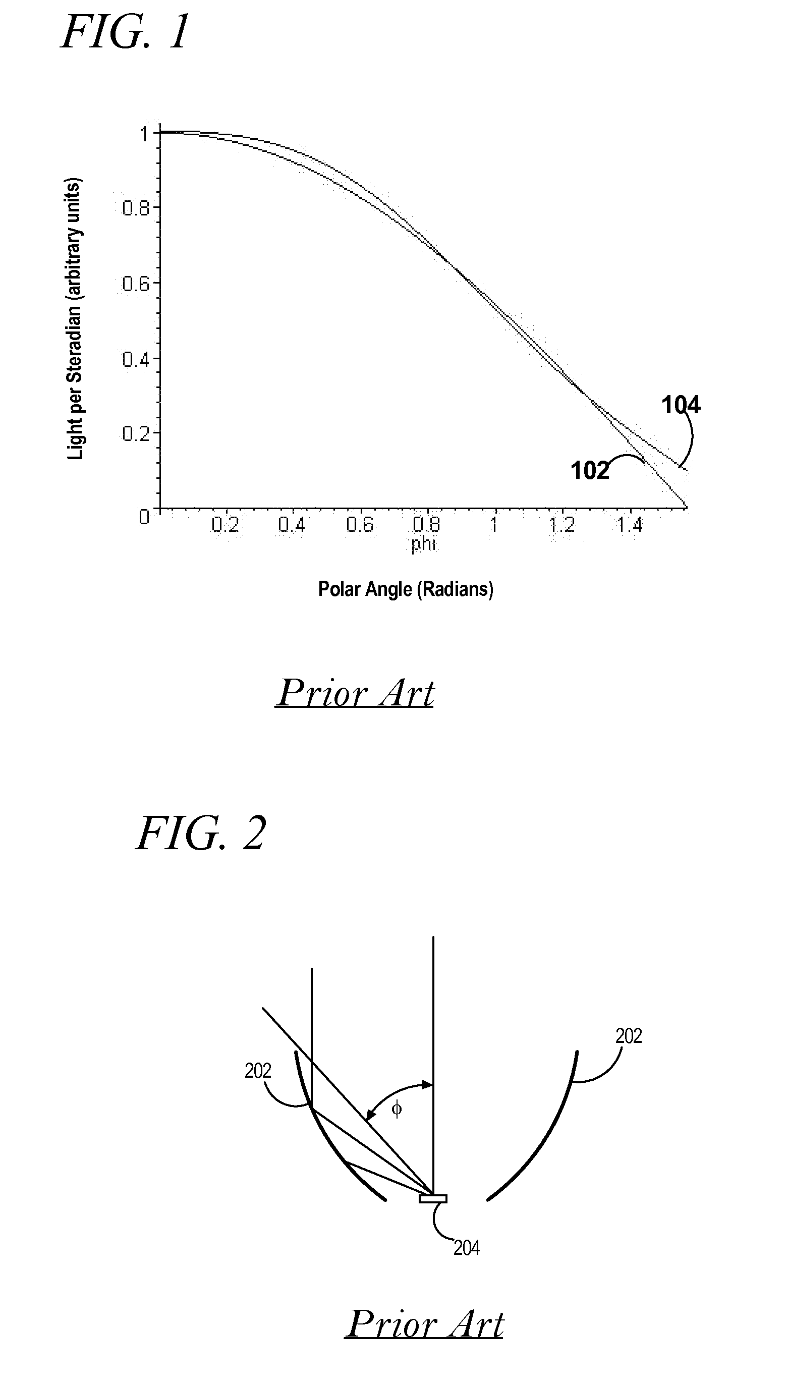
TABLE XPhi1_MIN0.0 radiansPhi1_MAX1.57 radians (90 degrees)Phi2_MIN0.0 radiansPhi2_MAX1.047 radians (60 degrees)rad_in(phi1)Plot 104 Quasi Lambertianrad_out(phi2)=1.0 (uniform goal)r1_ini(Phi1_MIN)3.0n11.497n21.0

fourth embodiment

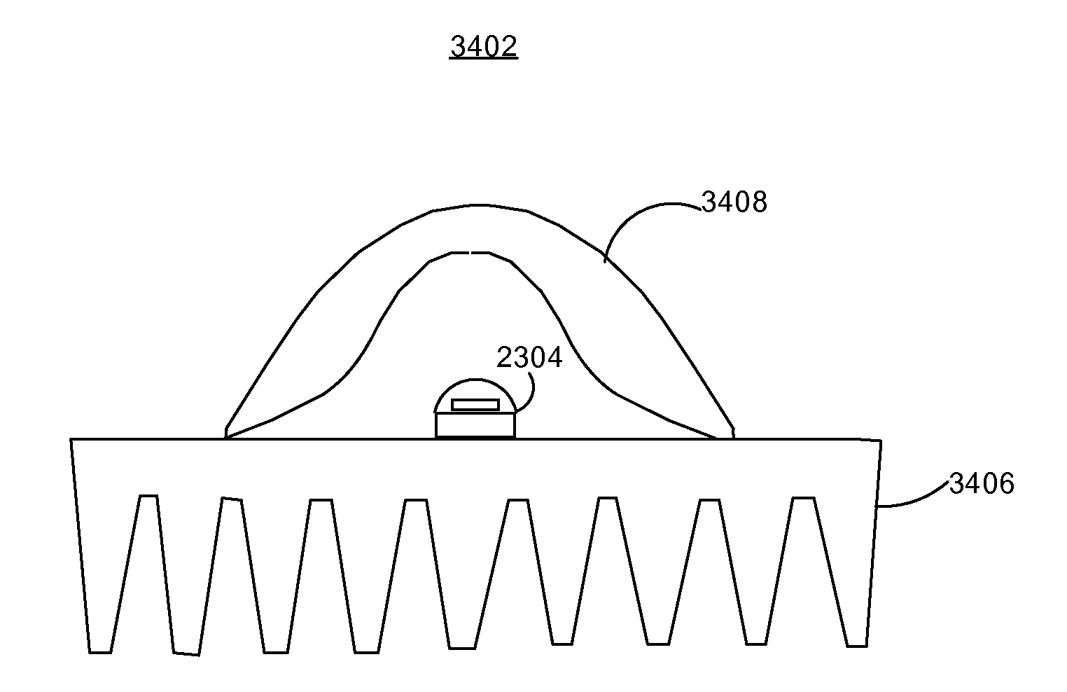
[0088]FIG. 28 shows generatrixes of surfaces 2802, 2804, 2806, 2808 of a lens 2800 with (TIR) wings according to the invention. The TIR wings include a TIR reflecting surface 2802 which reflects light through an exit surface 2804. A central refracting surface 2806 is defined by DE3. The central refracting surface 2806 handles an angular range of light up to a polar angle value phi1_switch and the TIR reflecting surface 2802 handles light beyond phi1_switch. A wing inner surface 2808 merely connects the exit surface 2804 and the central refracting surface 2806. DE4 is given below

DE4∂∂φ1r1=r1cot(-12φ1-12arcsin(n2sin(-φ2+phi_exit)n1)+12phi_exit)

[0089]where, phi1, r1, phi2 are the same as defined above; and

[0090]phi_exit is the angle between the upward facing surface normal ‘N’ to the exit surface 2804 and the Z-axis (measured in the clockwise direction, (see FIG. 28);

[0091]with initial condition r1_w_ini.

[0092]Table IV shows the inputs and radiant intensity functions for the lens 2800....


PUM


Abstract

Illumination lenses (1806, 1902, 2002, 2100, 2200, 2300, 2400, 2500, 2600, 2700, 2800, 3006, 3100) having surfaces shaped according to given differential equations in order to distribute light in a highly controlled manner with minimum reflection losses are provided. Both primary lenses and secondary lenses are provided. The secondary lenses include outer surfaces that are defined as loci of constant optical distance from an origin at which a light source is located. Versions are provided of both the primary and secondary lenses having Total Internal Reflection (TIR) wings. These are useful in the case that narrower distributions of light are required. A method of refining the shape of the lenses to obtain more obtain lenses that produce better fidelity ideal light distributions is also provided.

Description

RELATED APPLICATION DATA[0001]This application is based on U.S. provisional application Nos. 61 / 200,730 and 61 / 200,732.FIELD OF THE INVENTION[0002]The present invention relates to illumination optics especially suitable for use with Light Emitting Diodes.BACKGROUND OF THE INVENTION[0003]Traditionally Light Emitting Diodes (LEDs) have primarily been used as indicator lamps in electronic equipment. However recently the power and efficacy (e.g., lumens per watt of electrical power) has been increasing and LEDs have been identified as a possible replacement for inefficient incandescent lamps in certain applications. The light emitting region of an LED is small (e.g., in the range of 2 mm to 0.5 mm across in many cases) which in theory opens up the possibility for highly controlled distribution of light. However many of LED optics developed so far do not produce controlled distributions, rather they typically produce Gaussian like distributions which is the hallmark of somewhat uncontrol...

Claims


Application Information

Patent Timeline
IPC IPC(8): F21V13/04G02B3/02G02B3/04F21V5/04B29D11/00G05B13/04G06F17/10
CPCB29D11/00009F21V5/04G02B3/04G02B19/0028G02B19/0061F21Y2115/10
Inventor PREMYSLER, PHILIP
Owner PREMYSLER PHILIP
Why Eureka
Try Eureka