Apparatus and method for biasing a transducer

a transducer and biasing technology, applied in the field of apparatus and method for biasing a high input impedance device or circuitry, can solve the problems of increasing the load on the output of the voltage generator itself, undesirable sensitivity variation, and insufficient bias voltage generation to generate a stable sensitivity. the effect of no unnecessary loading

Active Publication Date: 2010-07-01
CIRRUS LOGIC INC
View PDF1 Cites 99 Cited by
  • Summary
  • Abstract
  • Description
  • Claims
  • Application Information

AI Technical Summary

Benefits of technology

[0034]The controlling step conveniently comprises the steps of: providing a second voltage generator for generating the first voltage, the second voltage generator receiving a third voltage; and controlling the second voltage generator using the calibration value and the first voltage. The method thus involves arranging a controllable voltage generator to feed into a stable voltage generator in a two stage process. Control is performed at relatively low voltages with no unnecessary loading on the relatively high voltage output.

Problems solved by technology

Such variation in sensitivity is undesirable in the end application, particularly in applications where multiple high input impedance devices and circuits are used together (for example, the use of MEMS microphones in mobile phones or headphones that have noise cancelling circuitry that requires a plurality of said microphones).
However, the output voltage of open-loop voltage generators is generally variable with manufacturing tolerances, temperature and / or load current, so the bias voltage generated is not stable enough to generate a stable sensitivity.
On the other hand, closed-loop voltage generators, where the voltage generator output is directly monitored and stabilised by a control loop, require control circuitry which increases the load on the output of the voltage generator itself, which adds components and hence cost, and also increases power consumption.

Method used


Image

  • Apparatus and method for biasing a transducer
  • Apparatus and method for biasing a transducer
  • Apparatus and method for biasing a transducer

Examples


Embodiment Construction

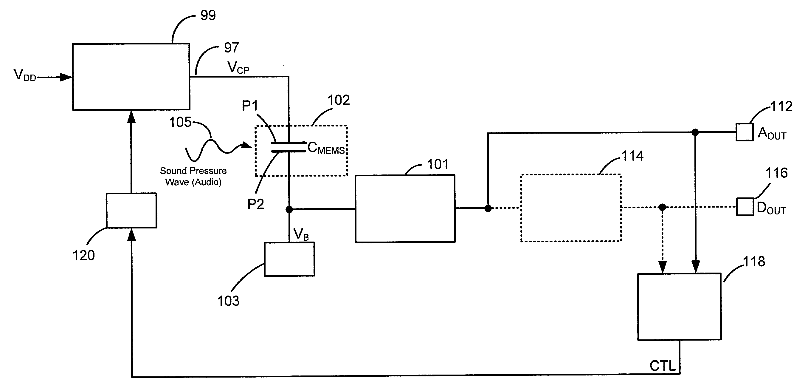
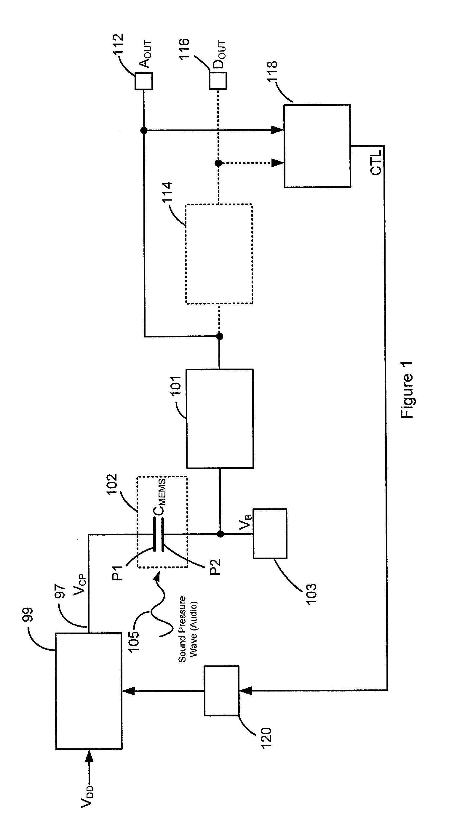
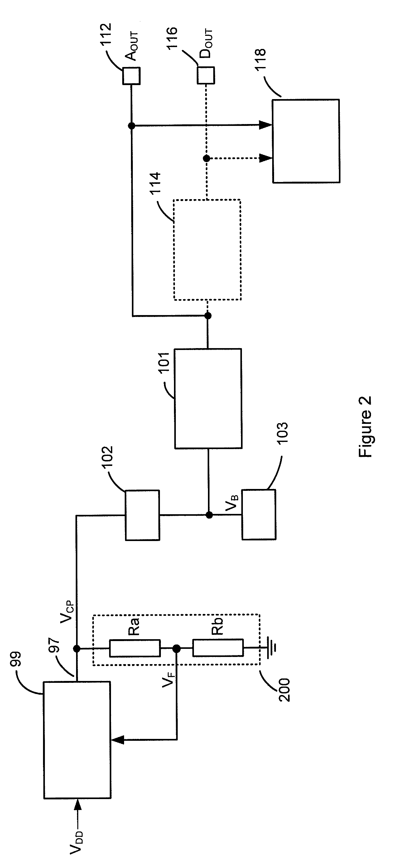
[0055]The description of the embodiments below will be made in relation to a high input impedance transducer in the form of a MEMS capacitive microphone. However, it will be appreciated that the invention is also applicable to other types of high input impedance transducers, devices, circuits, components and the like and not only MEMS capacitive transducers and not only microphones or audio applications. It is also noted that the detailed description will be made with reference to a voltage generator in the form of a charge pump, although it will be appreciated that the invention is equally applicable to other forms of voltage generating circuits. Furthermore, although the embodiments below will be described mainly in relation to fine tuning, trimming or adjusting (e.g. calibrating) a voltage generator during a testing or manufacturing stage, the invention is equally applicable to fine tuning, trimming or adjusting a voltage generator at any stage including, for example, during the ...


PUM


Abstract

An apparatus comprising a capacitive transducer, for example a MEMS microphone. A first voltage generator is connected to receive a first voltage (VDD*) and generate a second voltage (VCP) for biasing the capacitive transducer. A control circuit is adapted to, in use, control the first voltage (VDD*) based on a calibration value, wherein a different calibration value would lead to a different first voltage level and the calibration value is set such that an input signal of known amplitude produces an output signal of predetermined amplitude.

Description

BACKGROUND OF THE INVENTION[0001]1. Field of the Invention[0002]This invention relates to an apparatus and method for biasing a high input impedance device or circuitry, such as a capacitive transducer for example. In particular, the invention relates to the operation and adjustment or calibration of the output voltage of a voltage supply apparatus during, for example, the use or testing of such high input impedance devices or circuits.[0003]2. Description of the Related Art[0004]Consumer electronics devices are continually getting smaller and, with advances in technology, are gaining ever increasing performance and functionality. This is clearly evident in the technology used in consumer electronic products such as, for example, mobile phones, laptop computers, MP3 players and personal digital assistants (PDAs). Requirements of the mobile phone industry, for example, are driving components to become smaller with higher functionality and reduced cost. For example, some mobile phones...

Claims


Application Information

Patent Timeline
Patent Type & Authority Applications(United States)
IPC IPC(8): H04R3/00
CPCA61B8/4444H04R3/00H04R19/005H04R19/04H04R29/004A61B8/56B81B3/0027G05F1/461H02M3/07
Inventor STEELE, COLIN FINDLAYMACFARLANE, DOUGLAS JAMES WALLACE
Owner CIRRUS LOGIC INC
Why Eureka
Try Eureka