Perpendicular magnetic recording medium

Active Publication Date: 2010-07-01
FUJI ELECTRIC CO LTD
View PDF3 Cites 0 Cited by
  • Summary
  • Abstract
  • Description
  • Claims
  • Application Information

AI Technical Summary

Benefits of technology

[0018]By means of this invention, ferromagnetic coupling between magnetic recording layers in a perpendicular magnetic recording medium can be set appropriately, and moreover, by providing a high-Ku layer and a low-Ku layer, the index KuV can be improved and the average coercivity Hc of the magnetic recording layers overall can be lowered, so that the switching magnetic field of the magnetic recording medium can be lowered without detracting from thermal stability, and at the same time improvements in the noise characteristics, S/N characteristics, a

Problems solved by technology

However, when using conventional magnetic recording media employing in-plane magnetic recording, because of the problem of the “thermal fluctuation” phenomenon due to which recorded signals cannot be held with stability, a recording density limit was being approached.
As is clear from this index, in order to raise the recording density, the magnetization reversal unit is reduced, and thermal stability is also diminished, so that thermal fluctuations pose a problem even for perpendicular magnetic recording media.
Hence, when Ku is increased in order to maintain thermal stability, the magnetic field intensity necessary during recording increases, and when this increase i

Method used


Image

  • Perpendicular magnetic recording medium
  • Perpendicular magnetic recording medium
  • Perpendicular magnetic recording medium

Examples


embodiment 1

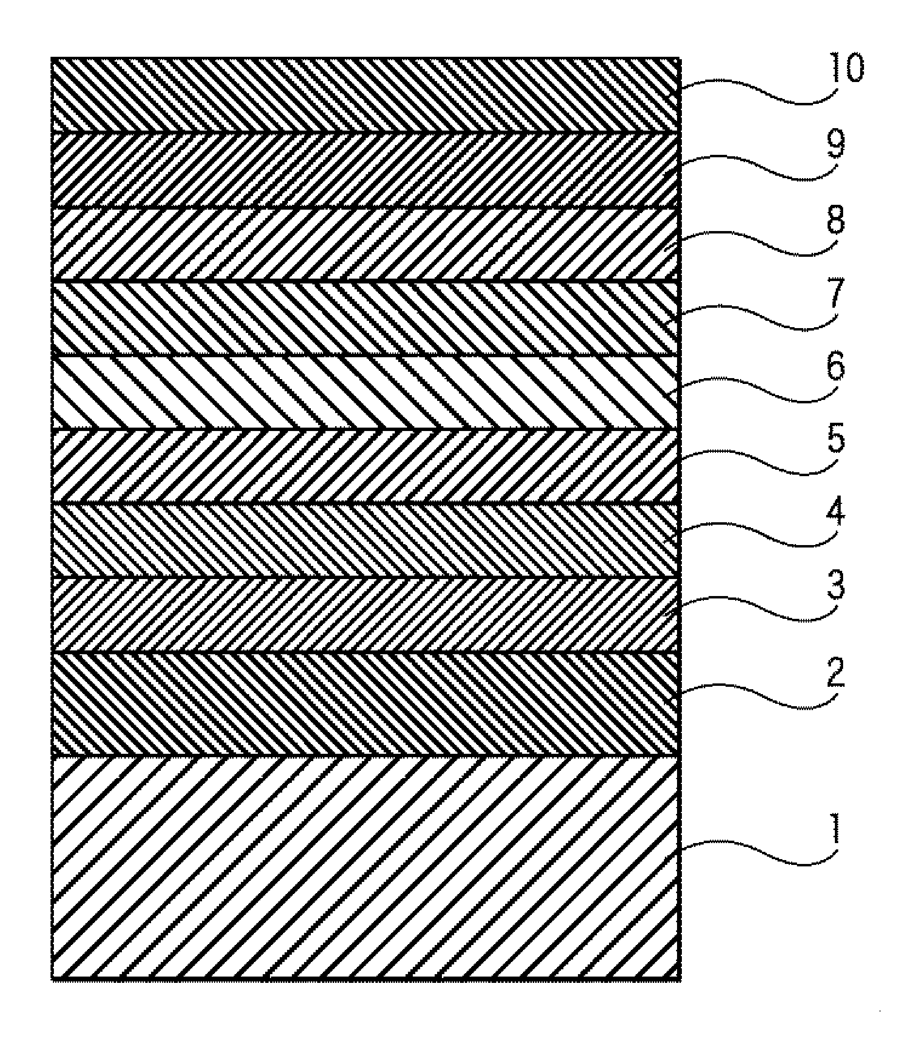
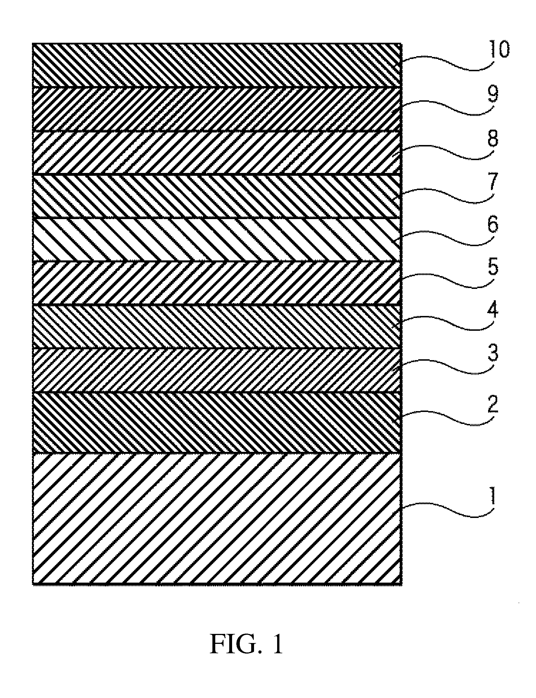
[0056]As the nonmagnetic substrate 1, an Al alloy plated with NiP and with a flat surface was used; after cleaning, the substrate was introduced into a sputtering device, and a Co—Zr—Nb target was used to deposit a CoZrNb amorphous soft magnetic backing layer 2 of thickness 40 nm. Next, a target of Ni—Fe—Si, which is a Permalloy system alloy, was used to deposit an NiFeSi underlayer 3 of thickness 10 nm. Then, a Ru target was used to deposit a Ru nonmagnetic intermediate layer 4 of thickness 10 nm. Then, a 93(Co-8Cr-20Pt)-7SiO2 target was used to deposit a granular-structure CoCrPt—SiO2 first magnetic recording layer 5 of film thickness 4 to 8 nm. Next, a Ru target was used to deposit a Ru coupling layer 6 of film thickness 0.2 nm. Then, a 93(Co-15Cr-10Pt)-7SiO2 target was used to deposit a granular-structure CoCrPt—SiO2 second magnetic recording layer 7 of film thickness 4.0 nm. Then, a 93(Co-20Cr-5Pt)-7SiO2 target was used to deposit a third magnetic recording layer 8 of film thic...

embodiment 2

[0062]Except for the fact that the CoZrNb amorphous soft magnetic backing layer 2 was not deposited, entirely the same processes as in Embodiment 1 were used to fabricate a magnetic recording medium.

embodiment 3

[0069]As the nonmagnetic substrate 1, an Al alloy plated with NiP and with a flat surface was used; after cleaning, the substrate was introduced into a sputtering device, and a Co—Zr—Nb target was used to deposit a CoZrNb amorphous soft magnetic backing layer 2 of thickness 40 nm. Next, a target of Ni—Fe—Si, which is a Permalloy system alloy, was used to deposit an NiFeSi underlayer 3 of thickness 10 nm. Then, a Ru target was used to deposit a Ru nonmagnetic intermediate layer 4 of thickness 10 nm. Then, a 93(Co-8Cr-20Pt)-7SiO2 target was used to deposit a granular-structure CoCrPt—SiO2 first magnetic recording layer 5 of film thickness 4 to 8 nm. Next, a Ru target was used to deposit a Ru coupling layer 6 of film thickness 0.2 nm. Then, a 93(Co-15Cr-10Pt)-7SiO2 target was used to deposit a granular-structure CoCrPt—SiO2 second magnetic recording layer 7 of film thickness 4.0 nm. A third magnetic recording layer 8 was not deposited, and finally, a carbon target was used to deposit a...


PUM


Abstract

A perpendicular magnetic recording medium, which includes a first magnetic recording layer, a second magnetic recording layer, and a third magnetic recording layer disposed sequentially on a nonmagnetic substrate, and a coupling layer formed between the first and second magnetic recording layers. The first, second and third magnetic recording layers have an easy axis of magnetization in a direction perpendicular to a film plane of the nonmagnetic substrate. The first and second magnetic recording layers are ferromagnetically coupled via the coupling layer.

Description

BACKGROUND OF THE INVENTION[0001]1. Field of the Invention[0002]This invention relates to perpendicular magnetic recording media mounted in various magnetic recording devices. More specifically, this invention relates to perpendicular magnetic recording media mounted in hard disk drives (HDDs) used as storage devices in computers, audio and video equipment, and similar.[0003]2. Description of the Related Art[0004]In recent years there has been a rapid increase in the recording density of hard disk drives (HDDs), and this trend is expected to continue. However, when using conventional magnetic recording media employing in-plane magnetic recording, because of the problem of the “thermal fluctuation” phenomenon due to which recorded signals cannot be held with stability, a recording density limit was being approached. Hence in order to address demands for substantial increases in recording densities, much research had been performed on perpendicular magnetic recording media, adopting t...

Claims


Application Information

Patent Timeline
IPC IPC(8): G11B5/706
CPCG11B5/65G11B5/66G11B5/678
Inventor SATO, AKIRATAKENOIRI, SHUNJISAKAI, YASUSHI
Owner FUJI ELECTRIC CO LTD
Why Eureka
Try Eureka