Fuel Cell Module

a fuel cell and module technology, applied in the field of fuel cell modules, can solve the problems of so as to achieve reduced heat exchange efficiency as well as power generation efficiency, impaired high efficiency self-sustained heating operation, and reduced utilization efficiency of oxygen-containing gas

Active Publication Date: 2010-07-01
KYOCERA CORP
View PDF6 Cites 34 Cited by
  • Summary
  • Abstract
  • Description
  • Claims
  • Application Information

AI Technical Summary

Benefits of technology

[0009]In the conventional fuel cell module 100 shown in FIG. 26, the upper end of the heat exchanger 120a and 120b and the bottom plate 142 of the oxygen-containing gas chamber 140 are welded and joined to each other at the flange portion. The oxygen-containing gas tends to leak from the welded portion 115. When the high temperature oxygen-containing gas having passed through the heat exchanger leaks, due to heat loss, not only the utilization efficiency of the oxygen-containing gas is reduced, but also the efficiency of heat exchange as well as power generation are reduced and a high efficiency self-sustained heating operation is impaired.

Problems solved by technology

When the high temperature oxygen-containing gas having passed through the heat exchanger leaks, due to heat loss, not only the utilization efficiency of the oxygen-containing gas is reduced, but also the efficiency of heat exchange as well as power generation are reduced and a high efficiency self-sustained heating operation is impaired.
Therefore, the structure of the fuel cell module 100 is complicated and a large number of component parts are needed.
Further, a large number of assembly steps for connecting, fixing and / or welding the component parts are required.
As a result, large costs are required for storing the component parts and manufacturing.
Therefore, there are problems such that the gas sealing reliability is reduced, while the manufacturing and assembling cost is increased.

Method used


Image

  • Fuel Cell Module
  • Fuel Cell Module
  • Fuel Cell Module

Examples


Embodiment Construction

[0090]Hereinafter, embodiments of the invention will be described with reference to the drawings. A solid-oxide fuel cell module of the invention is preferably applicable to a distributed power generation, particularly, to a 0.5 to 1.5 kW class domestic fuel cell module that performs a load following operation.

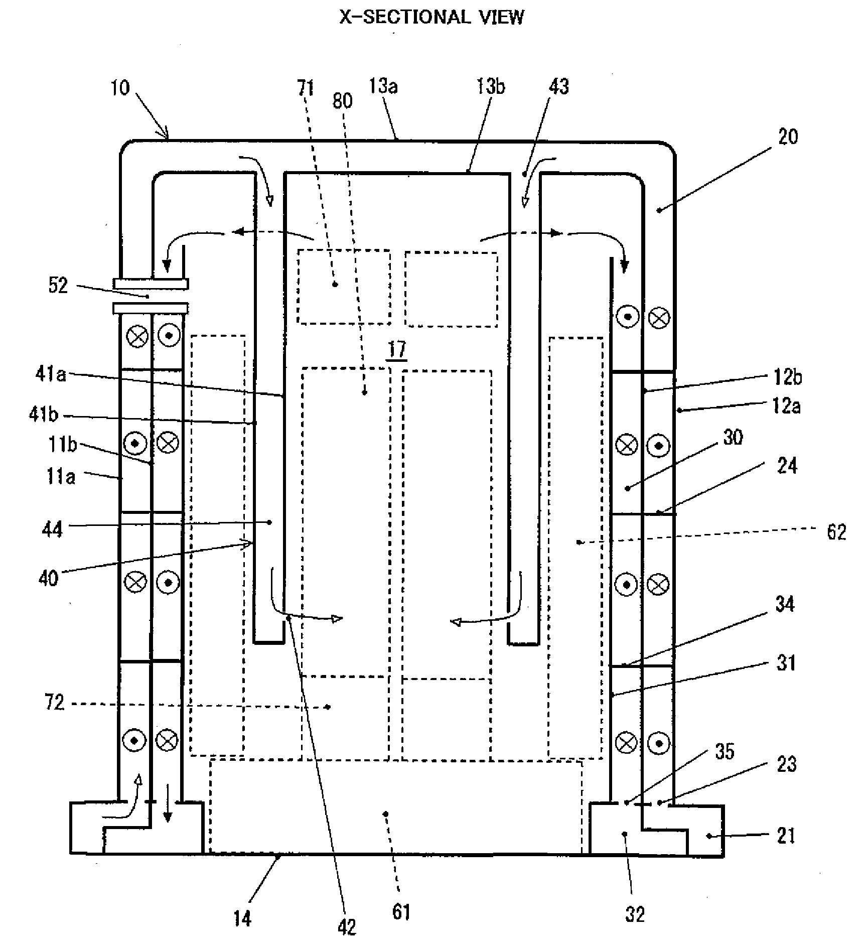
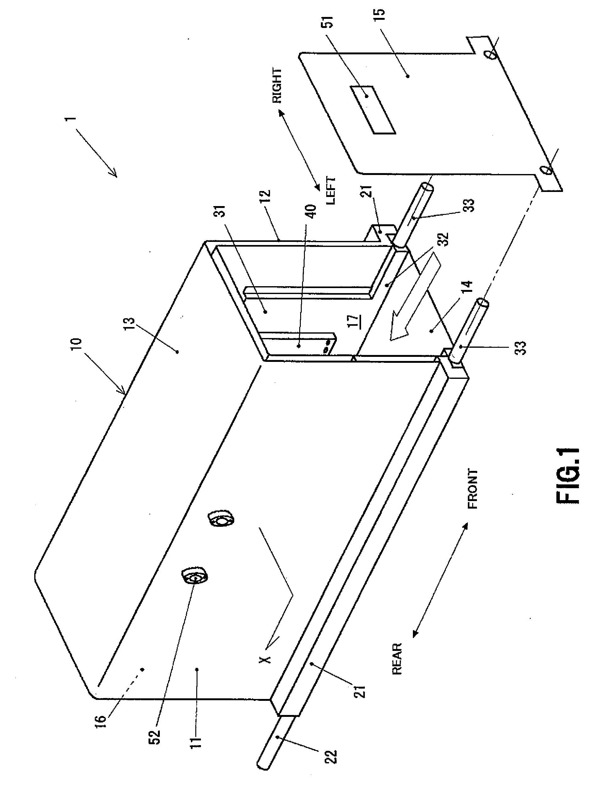
[0091]FIG. 1 is an external perspective view of an embodiment of a solid-oxide fuel cell module according to the invention. A fuel cell module 1 has a generally rectangular casing 10, and the casing 10 encloses a power-generating chamber 17. Although not shown in FIG. 1, the power-generating chamber 17 includes a cell stack having a plurality of solid-oxide fuel cells arranged in a line and a fuel cell stack device composed of a manifold (fuel gas case) and / or a reformer and the like (which will be described later in detail) disposed therein. Hereinafter, the casing 10 will be described while indicating the direction thereof; i.e., front-rear direction or right and left direct...


PUM

PropertyMeasurementUnit
temperatureaaaaaaaaaa
rectangular shapeaaaaaaaaaa

Abstract

To provide a fuel cell module structure including a heat exchanger capable of preventing leakage of oxygen containing gas in a flow path and reducing the cost. The fuel cell module, which includes: a power-generating chamber that receives fuel cells; and a casing having a generally rectangular shape enclosing the power-generating chamber, wherein right and left side walls and an upper wall of the casing are hollow walls constituted of an outer shell member and an inner shell member disposed parallel to each other with a predetermined distance therebetween to form a reaction gas circulation space, each of the outer shell member and the inner shell member is formed in a U-like shape in cross section, a reaction gas introduction member vertically extending downward from the inner shell member of the upper wall into the power-generating chamber and being communicated with the reaction gas circulation space to introduce a reaction gas into the power-generating chamber.

Description

BACKGROUND OF THE INVENTION[0001]1. Field of the Invention[0002]The present invention relates to a fuel cell module having a power-generating chamber containing solid-oxide fuel cells and a casing enclosing the same.[0003]2. Description of the Related Art[0004]FIG. 26 is a schematic sectional view showing a typical example of a conventional solid-oxide fuel cell module 100 (refer to Japanese Unexamined Patent Publication (Kokai)) No. 2005-123014, Japanese Unexamined Patent Publication (Kokai) No. 2005-158526 and the like).[0005]A metal casing 110, which has a generally rectangular shape and encloses a power-generating chamber 111, is provided with heat exchanger 120a and 120b disposed on four or two side faces. The power-generating chamber 111 includes therein, for example, four rows of cell stacks 80 of fuel cells arranged in a line, reformers 71 each disposed thereabove, and manifolds 72 each attached to the respective cell stacks 80. Each of the manifolds 72 is a fuel gas case. A...

Claims


Application Information

Patent Timeline
Patent Type & Authority Applications(United States)
IPC IPC(8): H01M8/02H01M8/24
CPCH01M8/0247H01M8/04014H01M8/04089H01M8/04201H01M8/0618H01M8/24H01M8/2484H01M8/2485H01M8/249H01M2008/1293H01M8/2425H01M8/0263H01M8/2475Y02E60/50H01M8/2432
Inventor ONO, TAKASHI
Owner KYOCERA CORP
Why Eureka
Try Eureka