
Composite fiber electrosurgical instrument

Inactive Publication Date: 2010-07-01
LOESER EDWARD A
View PDF18 Cites 9 Cited by
  • Summary
  • Abstract
  • Description
  • Claims
  • Application Information

AI Technical Summary

Benefits of technology

[0025]Each aspect described herein may provide a non-stick conductive surface. Also, the aspects described herein may enable an electrothermally conductive surface. Furthermore, the aspects described herein may be less expensive to produce than platinum plating, ceramic coating, or TEFLON® coating.

Problems solved by technology

Unfortunately, charred and necrosized tissue and cells can be generated by localized excessive thermal heating, wherein such tissue and cells tend to adhere to the surgical instrument such as the cutting edge of a surgical knife.
The presence of such tissue and cells on the working surface of the instrument interferes with subsequent hemostatic cutting by disrupting the current field and correspondingly reducing the efficiency and efficacy of the instrument.
Several proposals have been made to provide a non-stick surface to the active electrode area, however none is entirely satisfactory.
TEFLON® material is not always easy to apply and may vaporize in use exposing the patient or surgeon to certain risks.
Additionally, the TEFLON® coating is not a good conductor.
That, in turn, has limited the ability of the tip to conduct electricity uniformly across the surface.
Furthermore, application of a TEFLON® coating requires additional processing time and cost.
The plating or coating process can be quite complex and costly.
Indeed, platinum is itself quite costly.
Relatedly, ceramics can be quite brittle, thus exposing the patient to risk of injury if pieces of ceramic chip or break off from the tip.

Method used


Image

  • Composite fiber electrosurgical instrument
  • Composite fiber electrosurgical instrument
  • Composite fiber electrosurgical instrument

Examples


Embodiment Construction

[0031]The invention will now be described below by way of non-limiting examples thereof with reference to the accompanying drawings.

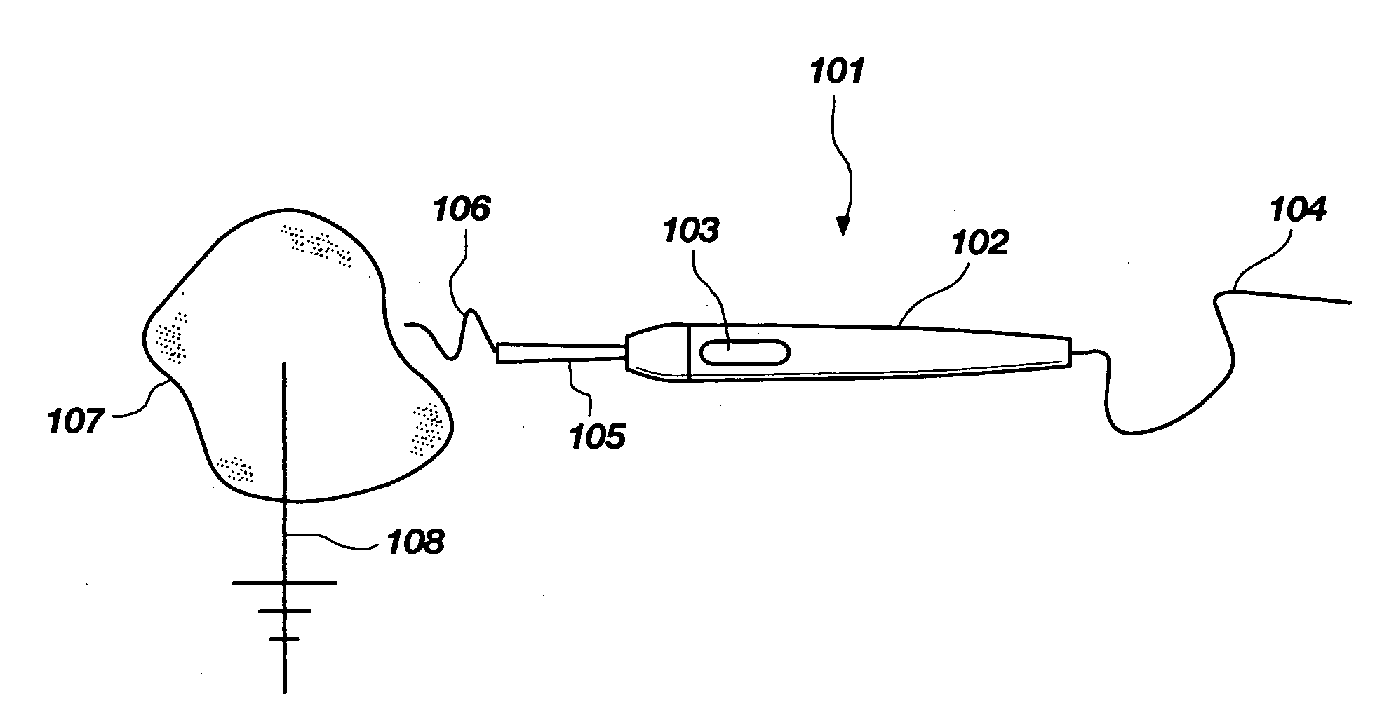
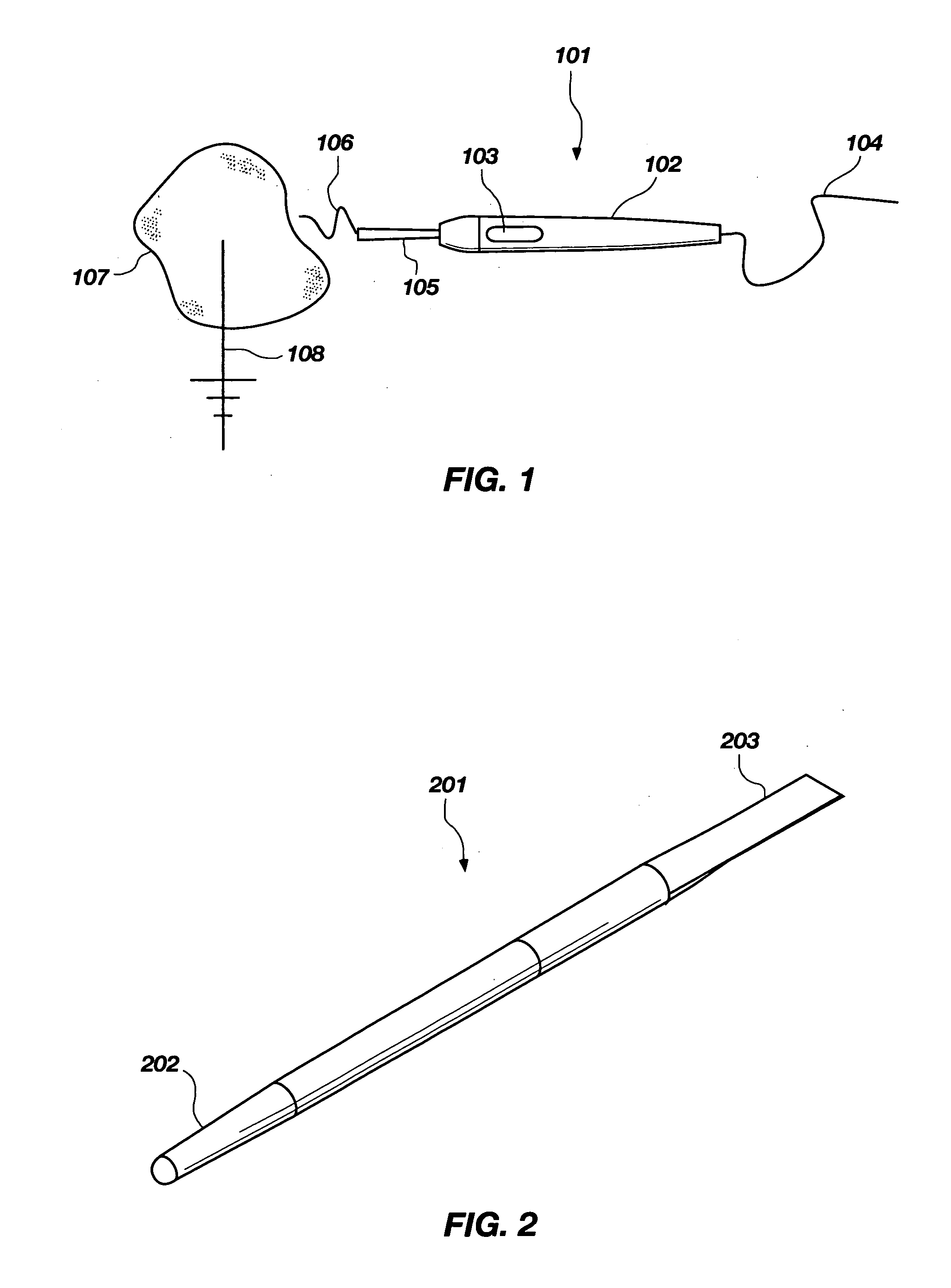
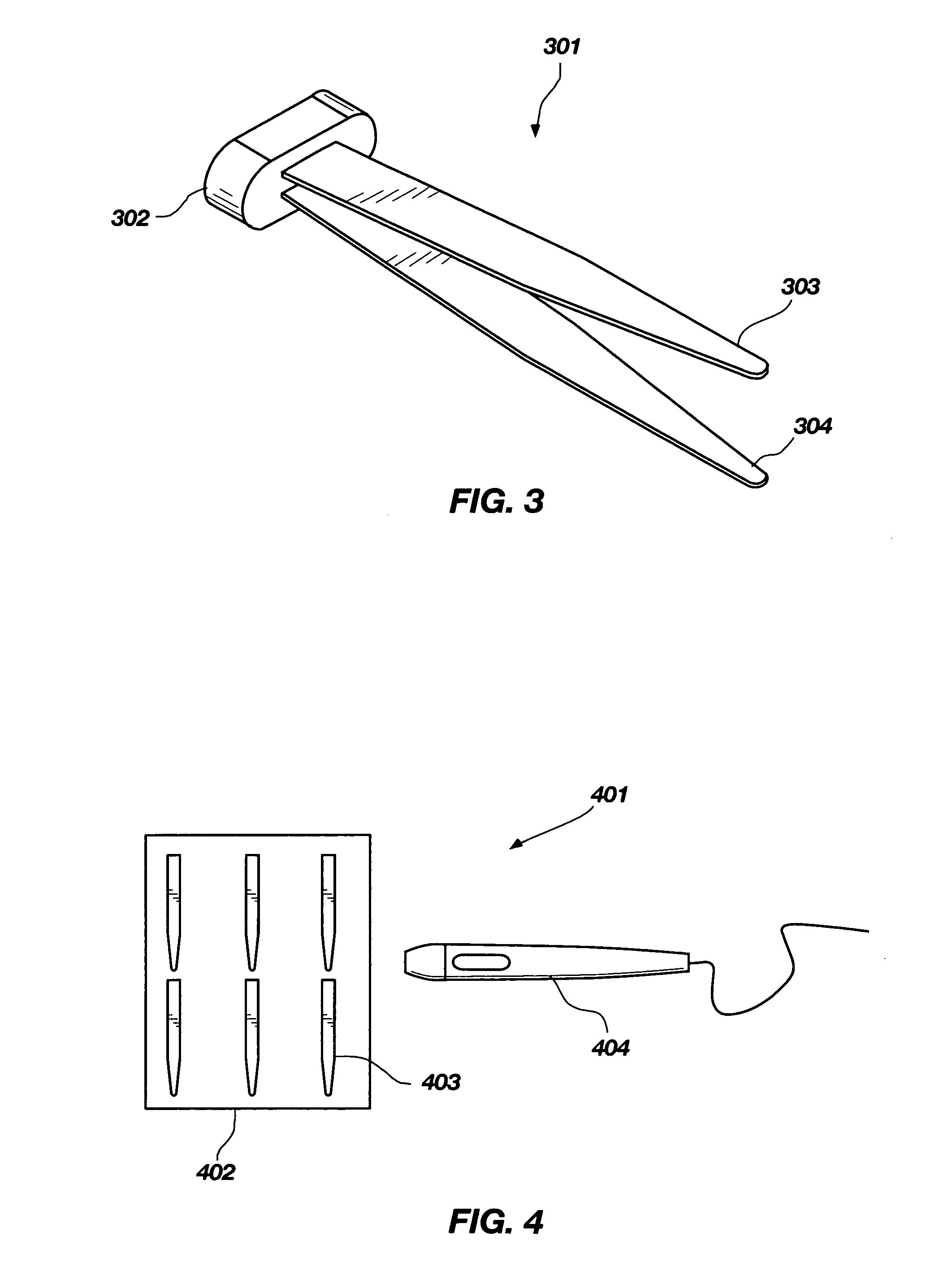
[0032]With reference to FIG. 1, there is shown a surgical instrument (e.g., an electric knife), generally designated at 101 and comprising an electric knife body portion 102 adapted for holding and manipulating the surgical instrument, wherein the body portion 102 insulates an electrically conductive core (not shown), a power control interface 103 for adjusting the intensity of electrical current flowing through the electrically conductive core, a power cord 104 intended to connect to an electric operating apparatus (not shown) and supply electric current to the electrically conductive core, and a tip (e.g., a tip electrode) 105 which at the distal end of the surgical instrument, wherein the tip can be monopolar (shown) or bipolar (not shown, see FIG. 3) and receives current from the conductive core. In aspects of the invention, the tip 105 is physicall...


PUM

PropertyMeasurementUnit
Coloraaaaaaaaaa
Antimicrobial propertiesaaaaaaaaaa
Opacityaaaaaaaaaa

Abstract

Described is a surgical instrument for electrocauterization (e.g., an electric knife), the surgical instrument including: a body portion for holding and controlling the surgical instrument, and, physically attached thereto, a radio-opaque tip for cauterizing living body tissue, wherein at least the tip comprises a silicon material. In such an instrument, the tip is typically a tip electrode. Aspects of the invention may also comprise a tip (e.g., a tip electrode) made of a composite fiber and colored. Aspects of the invention may also comprise a tip made of at least one material selected from the group consisting of M60 pitch fiber, metal coated carbon fiber, metal impregnated into fiber, AS4 carbon fiber, polyacrylonitrile fiber, shaped vinyl carbon fiber, and combinations thereof. Also described are methods of making a surgical instrument for electrocauterization, as well as methods of electrocauterization.

Description

PRIORITY CLAIM[0001]This application claims the benefit of U.S. Provisional Patent Application Ser. No. 60 / 937,651, filed on Jun. 29, 2007, titled “Composite Fiber Electrosurgical Instrument and Associated Methods”, the contents of the entirety of which are incorporated herein by this reference.TECHNICAL FIELD[0002]The invention relates generally to surgical instruments and associated methods, and, more particularly, to electrosurgical instruments with advantageous material properties.BACKGROUND[0003]Medical instrument coatings are applied in a variety of applications. One specialized type of medical instrument is an electrosurgical instrument such as an electric knife often referred to as an “RF scalpel.”[0004]Electrosurgical instruments are well known in the medical arts for incising soft patient tissue with concurrent transmission of electrical energy to the contacted tissue to cauterize small blood vessels and thereby minimize bleeding. Such instruments use a relatively high fre...

Claims


Application Information

Patent Timeline
IPC IPC(8): A61B18/14
CPCA61B17/30A61B17/3211A61B18/1402A61B2017/00473A61B2018/00107A61B2018/00125A61B2090/3966A61B2018/00922A61B2018/1412C22C47/04C22C47/08A61B90/92A61B2018/00595
Inventor LOESER, EDWARD A.
Owner LOESER EDWARD A
Learn More