
Remotely controlled ignition system for pyrotechnics

a remote control and ignition system technology, applied in the direction of launching weapons, ammunition fuzes, lighting and heating apparatus, etc., can solve the problems of time-consuming and cumbersome, manual firing methods are obvious safety issues, and digital systems are very expensiv

Active Publication Date: 2010-07-08
DEYE JAMES G
View PDF8 Cites 5 Cited by
  • Summary
  • Abstract
  • Description
  • Claims
  • Application Information

AI Technical Summary

Problems solved by technology

The digital systems are very expensive and are typically used with pyro-musical productions.
While manual firing is still the least expensive method of igniting pyrotechnic devices, the manual firing method presents obvious safety issues from the inability to ignite the fireworks remotely.
The labor for wiring each of these E-matches to the firing system is very time-consuming and cumbersome, and results in many wires disposed above the firing mortars of the pyrotechnic devices.
It has been estimated that approximately half of the labor of setting up a pyrotechnic show is due to the wiring of these devices.

Method used


Image

  • Remotely controlled ignition system for pyrotechnics
  • Remotely controlled ignition system for pyrotechnics
  • Remotely controlled ignition system for pyrotechnics

Examples


Embodiment Construction

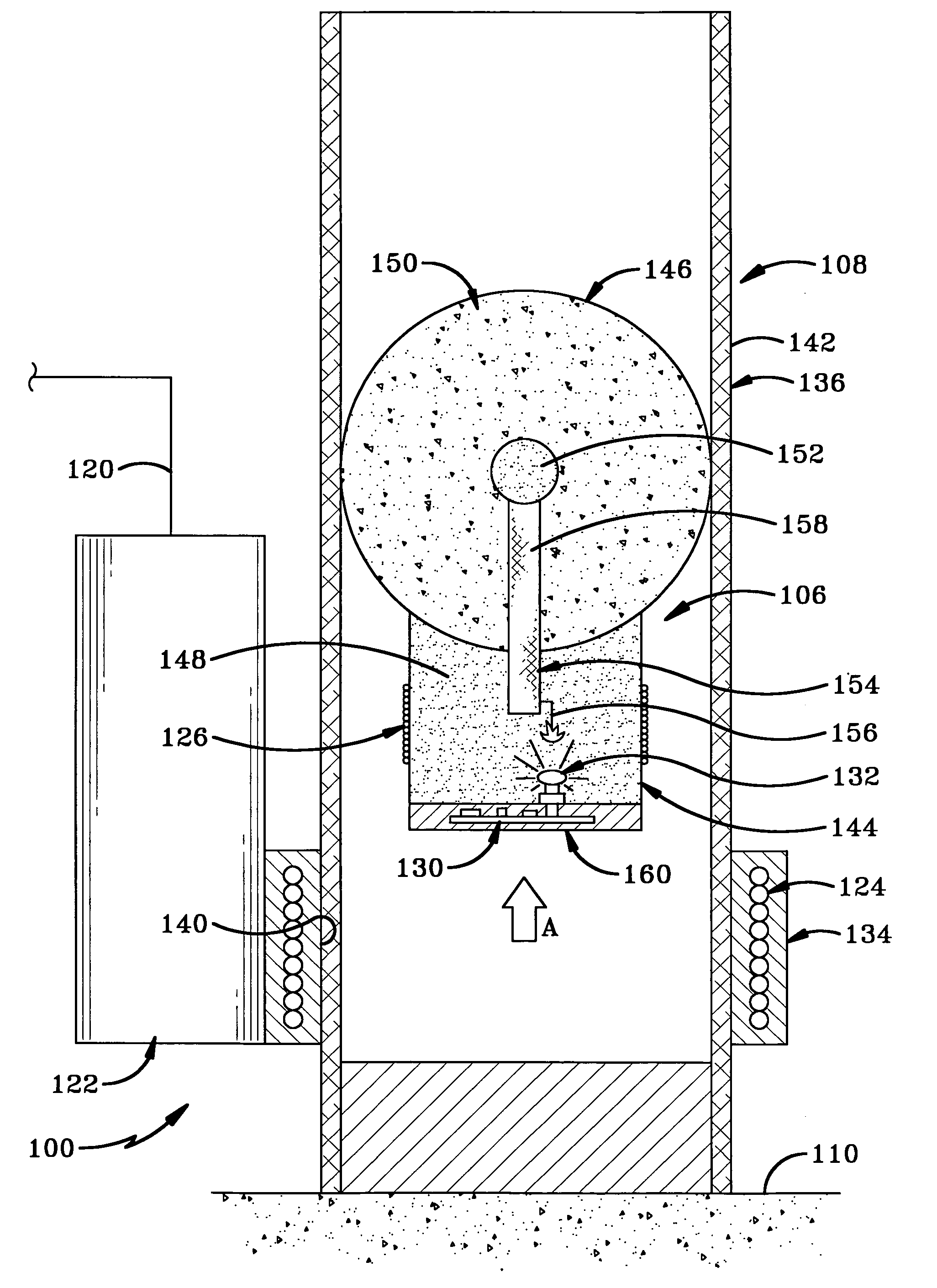
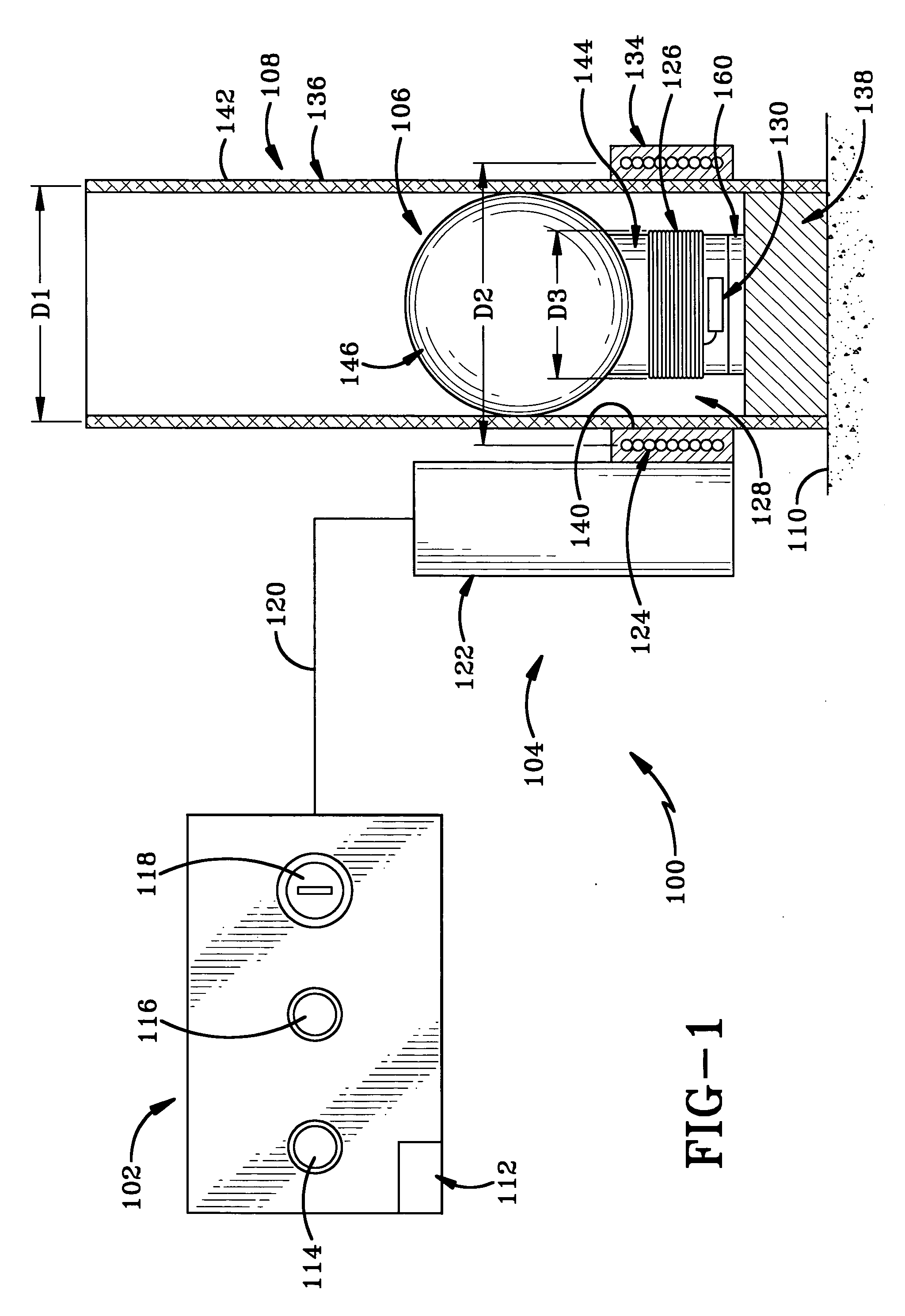
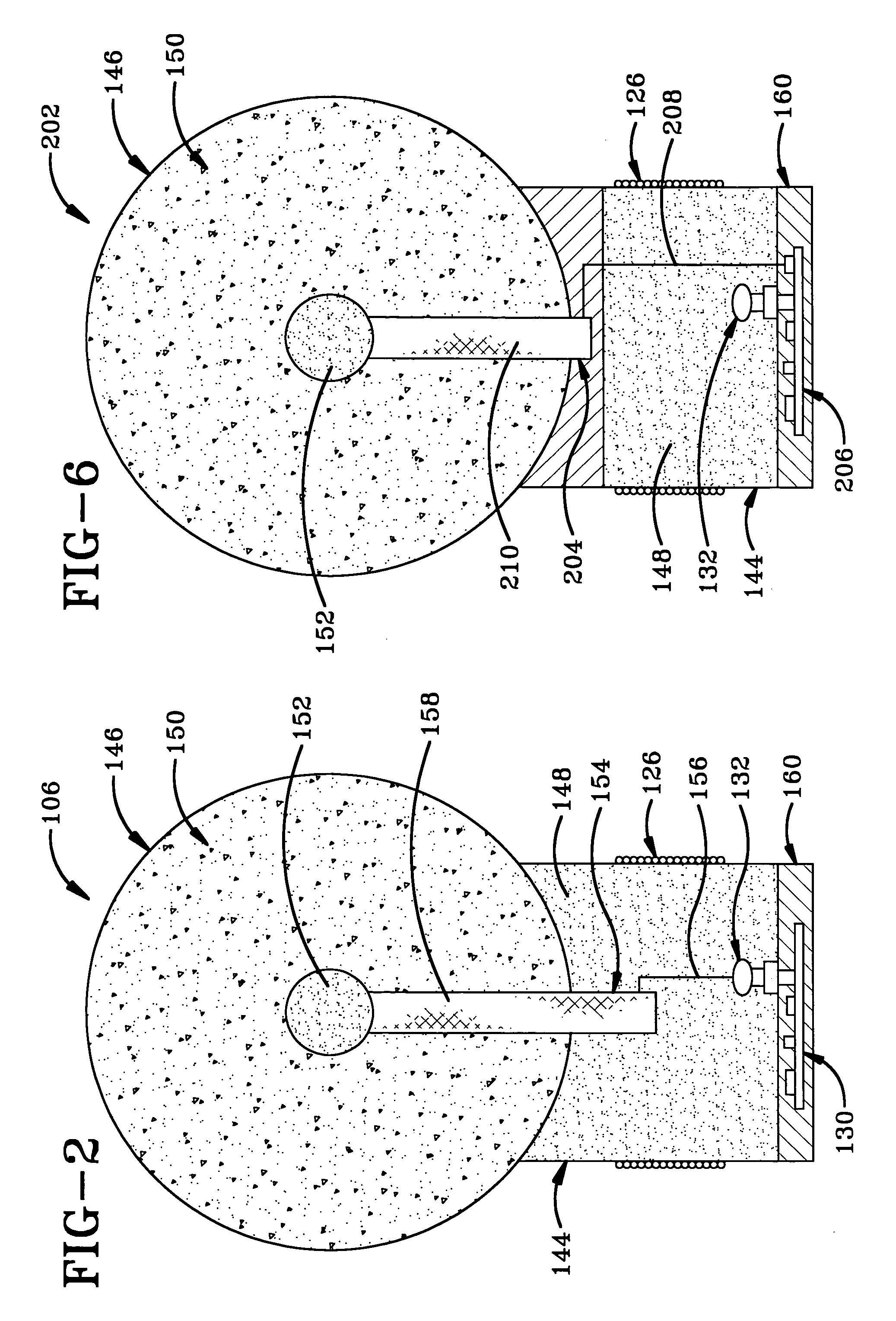
[0025]A first embodiment of the ignition system of the present invention is indicated generally at 100 in FIGS. 1-2; a second embodiment is indicated generally at 200 in FIGS. 6-7; a third embodiment is indicated generally at 300 in FIG. 10; a fourth embodiment is indicated generally at 400 in FIG. 11; a fifth embodiment is indicated generally at 500 in FIG. 12; and a sixth embodiment is indicated generally at 600 in FIG. 13. Each of said ignition systems is configured to remotely ignite pyrotechnic devices.

[0026]With reference to FIG. 1, ignition system 100 includes an ignition control 102 and an ignition communication pathway 104 in communication with control 102 for igniting or shooting a pyrotechnic device 106 from a firework mortar 108 disposed on a launch surface 110, which may be the ground or any other suitable structure known in the art. Control 102 includes a power supply 112, a charge button 114, a fire button 116 and an on / off key switch 118. Communication pathway 104 in...


PUM


Abstract

A remote pyrotechnic ignition system includes a power supply for producing an electrical current in a transmitting induction coil to induce an electrical current in a receiving induction coil for igniting a pyrotechnic device. Thus, a wireless ignition communication section allows pyrotechnic mortars to be reused and substantially reduces set-up time by eliminating the wiring of fireworks normally required for a pyrotechnic production. Optionally, a capacitor is charged by the power source via a charging circuit and discharged via a firing circuit to produce the electric current in the transmitting coil in a pulse. The capacitor provides a two-stage firing safety feature. An electronic control device such as a circuit board may be mounted on the pyrotechnic device for controlling ignition of the pyrotechnic device and is especially useful in controlling ignition sequencing and overall ignition timing of a lift charge and burst charge of the pyrotechnic device.

Description

CROSS REFERENCE TO RELATED APPLICATIONS[0001]This application claims priority from U.S. Provisional Application Ser. No. 60 / 708,935 filed Aug. 17, 2005; the disclosure of which is incorporated herein by reference.BACKGROUND OF THE INVENTION[0002]1. Technical Field[0003]The invention relates generally to a remotely controlled ignition system for pyrotechnic devices. More particularly, the invention relates to such a control system which is capable of wirelessly igniting pyrotechnic devices. Specifically, the invention relates to such a system where ignition is accomplished via electromagnetic induction.[0004]2. Background Information[0005]Ignition systems for fireworks or pyrotechnic devices are within three primary categories, namely manual firing, electrical firing and digital firing. Manual firing is the age-old process of igniting a fuse with a torch or some sort of hand lighter whereby a flame is the catalyst for igniting the fuse. In more recent decades, electrical firing has b...

Claims


Application Information

Patent Timeline
Patent Type & Authority Applications(United States)
IPC IPC(8): F42C19/12
CPCF41A19/63F41F1/06
Inventor DEYE, JAMES G.
Owner DEYE JAMES G
Learn More