
Phase-discriminating device and method

a phase-discrimination and device technology, applied in the direction of pulse automatic control, digital transmission, instruments, etc., can solve the problems of additional power consumption and automatic gain control, heavy computation storage, etc., and achieve high accuracy, noise robust property, and high accuracy.

Active Publication Date: 2010-07-08
NAT APPLIED RES LAB
View PDF6 Cites 6 Cited by
  • Summary
  • Abstract
  • Description
  • Claims
  • Application Information

AI Technical Summary

Benefits of technology

[0007]It is an object of the present invention to provide a phase-discriminating device and method, which is developed based on the digital perspective for a one-bit ADC processing receiver. In noiseless or high signal-to-noise ratio (SNR) environments, the present phase-discriminating device of the present invention achieves high accuracy than that of the typical arctangent phase-discriminating (APD) device up to several orders with sufficient samples since the accuracy of the APD device is bounded due to quantization loss. The present phase-discriminating device also has the high accuracy property in noiseless (or high SNR) environments and the noise robust property. The complexity and the computation load of the present phase-discriminating device are much less than those of the conventional APD device, and the feasibility in the one-bit processing receiver is very attractive due to avoidance of the automatic gain control (AGC), the efficient bit-wise processing and the cost-down implementation, such as the gate count reduction and the simple one-bit operation design, in the field programmable gate array (FPGA) and the application-specific integrated circuit (ASIC). The present phase-discriminating device is widely implemented in the fields of the communication, the digital signal processing, the software-defined receiver, the sensor-network, the position and the navigation.

Problems solved by technology

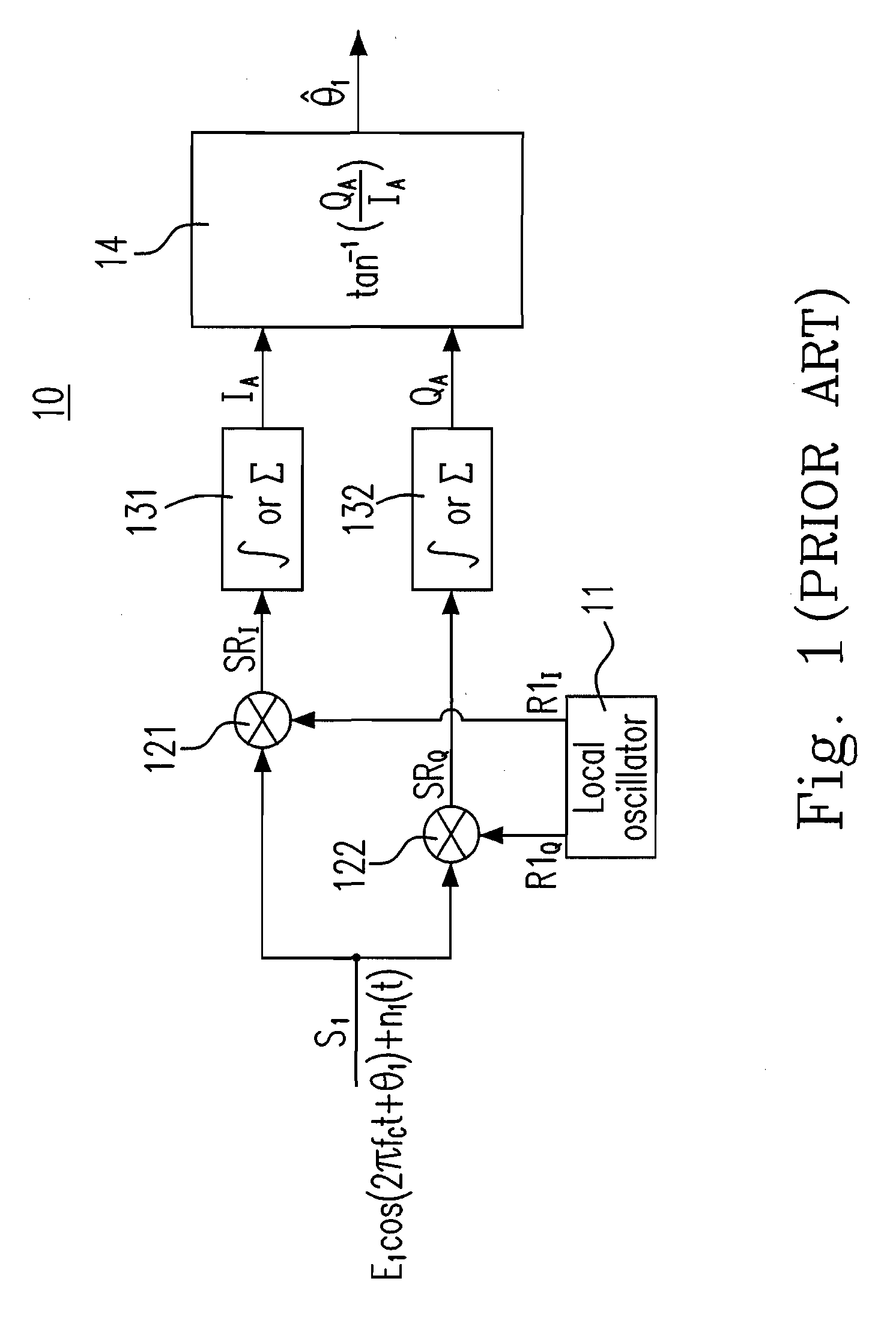
However, the arctangent operation tan−1(QA / IA) is complex due to the nonlinear form, and thus performing the arctangent operation tan−1(QA / IA) requires heavy computation storage, additional power consumption and automatic gain control.

Method used


Image

  • Phase-discriminating device and method
  • Phase-discriminating device and method
  • Phase-discriminating device and method

Examples


Embodiment Construction

[0020]The present invention will now be described more specifically with reference to the following embodiments. It is to be noted that the following descriptions of preferred embodiments of this invention are presented herein for the purposes of illustration and description only; it is not intended to be exhaustive or to be limited to the precise form disclosed.

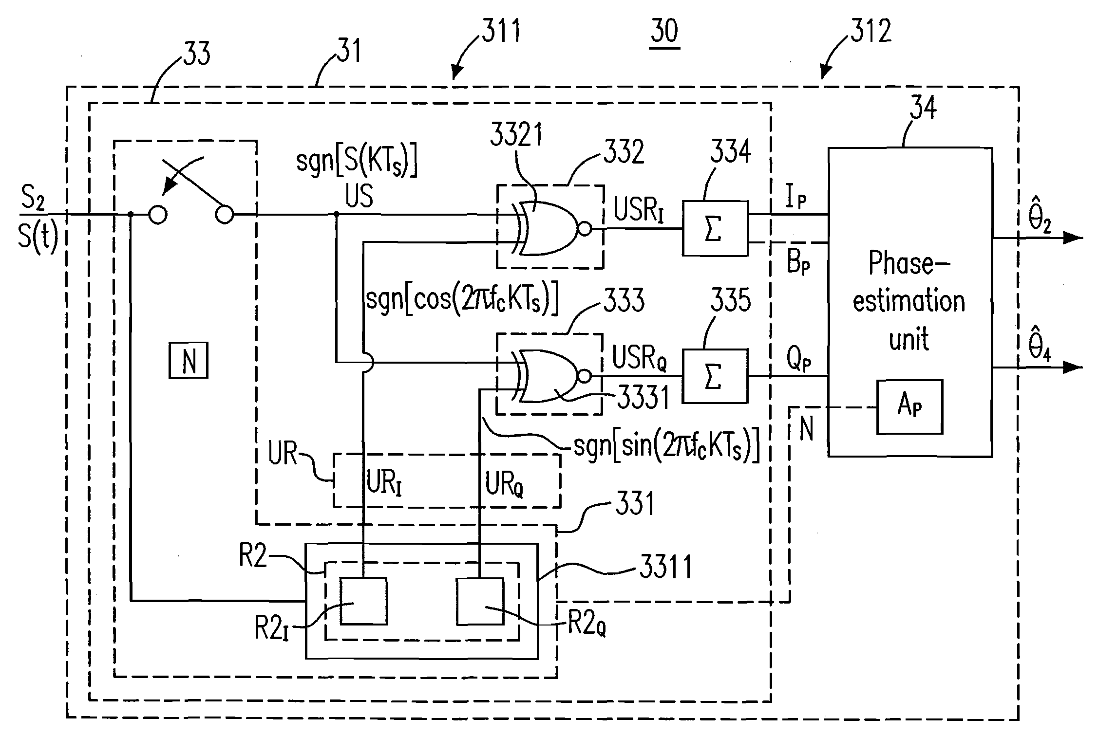
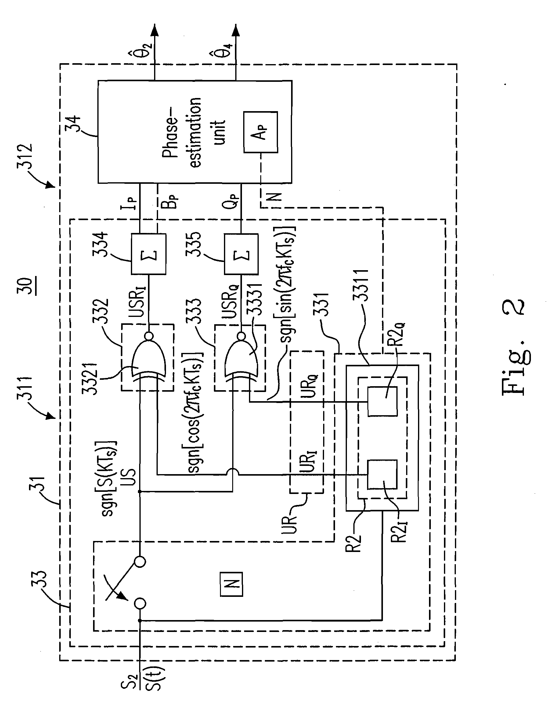
[0021]Please refer to FIG. 2, which is a schematic diagram showing a phase-discriminating device 30 of the present invention. As shown, the phase-discriminating device 30 includes a phase-discriminating unit 31. The phase-discriminating unit 31 receives an input signal S2 and produces an estimated phase {circumflex over (θ)}2 (or {circumflex over (θ)}4 in another embodiment) of the input signal S2, wherein the input signal S2 has a carrier frequency fC and a phase θ2. For instance, the input signal S2 may be expressed as the signal S(t)=E2 cos(2 pfCt+θ2)+n2(t), wherein E2 is the signal amplitude, n2(t) is the added Gaussian ...


PUM


Abstract

A high-accuracy and computational efficient phase-discriminating device is provided and includes a phase-discriminating unit. The phase-discriminating unit converts an input and a reference signals into an input and a reference sequences respectively by a one-bit A / D conversion operation, determines a first value, an in-phase component and a quadrature component of the input signal in response to the input and the reference sequences, and produces an estimated phase of the input signal according to a relation among the first value, the in-phase component and a polarity of the quadrature component, wherein the first value is a certain integer being one of a first integer and a second integer, the first integer is a sampling count of the one-bit A / D conversion operation for producing the input sequence, and the second integer is a summation of an absolute value of the in-phase component and that of the quadrature component.

Description

FIELD OF THE INVENTION[0001]The present invention relates to a phase-discriminating device and method, and more particularly to a phase-discriminating device and method for applying to a radio frequency receiving system.BACKGROUND OF THE INVENTION[0002]Please refer to FIG. 1, which is a schematic diagram showing a conventional arctangent phase-discriminating (APD) device. As shown, the APD device 10 includes a local oscillator 11, two multiplication circuits 121 and 122, two integration circuit 131 and 132, and a phase-estimating unit 14. The APD device 10 receives an input signal S1 and produces an estimated phase {circumflex over (θ)}1 of the input signal S1, wherein the input signal S1 has a carrier frequency fC and a phase θ1. For instance, the input signal S1 may be expressed as {E1 cos(2pfCt+θ1)+n1(t)}, wherein E1 is the signal amplitude, n1(t) is the added Gaussian noise, and t is the time.[0003]The local oscillator 11 produces an in-phase reference wave R1I and a quadrature ...

Claims


Application Information

Patent Timeline
IPC IPC(8): H03D13/00
CPCH03D13/006
Inventor CHANG, CHIEH-FUYANG, RU-MUHKAO, MING-SENG
Owner NAT APPLIED RES LAB
Learn More