Integrated Microminiature Relay

a micro-relay and micro-actuation technology, applied in electromagnetic relays, electromagnetic relay details, electrical apparatus, etc., can solve the problems of substantial decoupling of operating characteristics from deleterious effects, difficult structure, inconsistent operating characteristics, etc., and achieve the effect of efficient channeling the magnetic field

Active Publication Date: 2010-07-08
HT MICROANALYTICAL +1
View PDF44 Cites 16 Cited by
  • Summary
  • Abstract
  • Description
  • Claims
  • Application Information

AI Technical Summary

Benefits of technology

[0014]The present invention provides a microfabricated micro-relay that overcomes some of the limitations and drawbacks of the prior art. Embodiments of the present invention comprise: (1) a magnetically actuated electrical switch having a moving contact that selectively moves in a plane parallel to its substrate; (2) one or more integrated planar coils for generating a magnetic field that actuates the electrical switch; and (3) a closed magnetic circuit for efficiently channeling the magnetic field through the electrical switch.

Problems solved by technology

Using planar processing to add an efficient magnetic circuit having a compact magnetic path and large cross section area to such a structure is a challenge, however.
Such variation can result in inconsistent operating characteristics even among micro-relays of the same design.
As a result, the operating characteristics are substantially decoupled from deleterious effects due to film stress, thickness variations, and the like.
Implementing an electromagnetic coil within a batch wafer-level process can be quite challenging, however, due to the three-dimensional character of such a coil and the need to efficiently magnetically couple it to the movable magnetic element.
Thus, unfortunately, it is difficult at best to produce a practical integrated coil that can reliably actuate these switching elements.
As a result, micro-relays in the prior art have typically relied upon poorly coupled coils or external, non-integrated coils to provide the magnetic field for actuation.
With a poorly coupled coil, however, the consequent large electrical power required to energize the relay is a significant drawback.
The use of an externally configured coil not only adds significant packaging cost and size, but typically poor assembly tolerances can lead to significant variation in the operating characteristics of micro-relays of the same design.

Method used


Image

  • Integrated Microminiature Relay
  • Integrated Microminiature Relay
  • Integrated Microminiature Relay

Examples


Embodiment Construction

[0031]The following terms are defined for use in this Specification, including the appended claims:[0032]Electrically connected is defined as a state in which two or more points are connected such that they are at substantially the same voltage level at any current level. This can be via direct physical contact (e.g., a contact pad physically coupled with an electrical via, etc.) or through an electrically conductive intermediate (e.g., nodes of a circuit interconnected by a conductive wire or trace, etc.).[0033]Electrically coupled is defined as a state in which two points are in electrical communication. This can be via direct physical contact (e.g., a plug in an electrical outlet, etc.), via an electrically conductive intermediate (e.g., electrical devices connected by a conductive wire or trace, etc.), or via intermediate devices, etc. (e.g., electrical devices connected through a resistor, inductor, etc.).

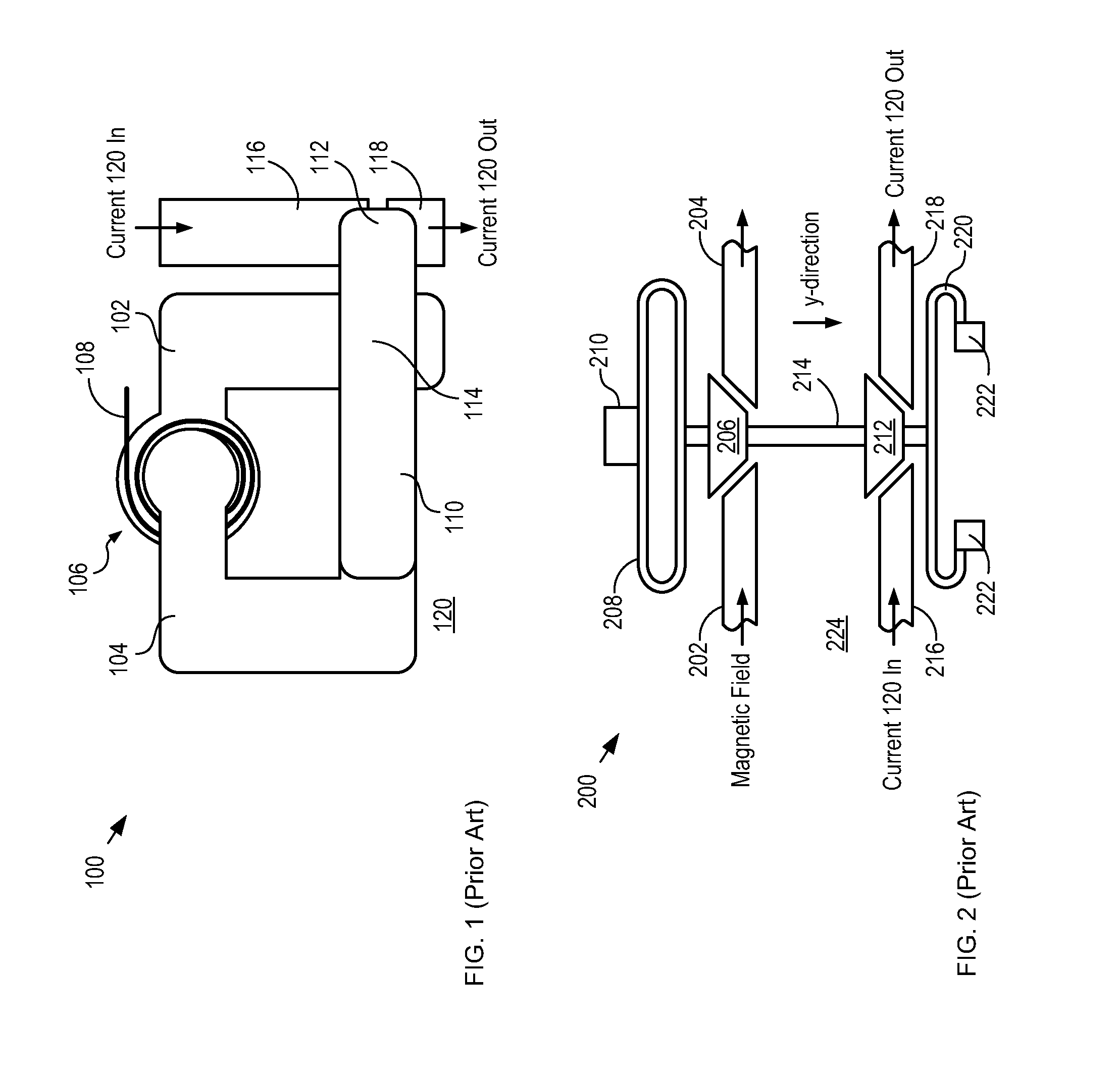
[0034]FIG. 1 depicts a schematic drawing of a first micro-relay in accord...


PUM


Abstract

A micro-relay that overcomes some of the limitations and drawbacks of the prior art is disclosed. The micro-relay comprising: (1) a first substrate comprising one or more monolithically integrated planar coils for generating a magnetic field; and (2) a second substrate comprising a magnetically actuated switch having a moving contact that selectively moves in a plane parallel to its substrate. The first and second substrate are aligned and bonded to collectively provide a closed magnetic circuit that efficiently channels the generated magnetic field through the switch.

Description

CROSS REFERENCE TO RELATED APPLICATIONS[0001]This case is a continuation-in-part of co-pending U.S. patent application Ser. No. 12 / 406,937, filed Mar. 18, 2009, which is incorporated by reference herein.[0002]The underlying concepts, but not necessarily the language, of the following cases are incorporated by reference:[0003](1) U.S. Pat. No. 6,094,116, issued Jul. 25, 2000; and[0004](2) U.S. Pat. No. 6,366,186, filed Apr. 2, 2002.If there are any contradictions or inconsistencies in language between this application and one or more of the cases that have been incorporated by reference that might affect the interpretation of the claims in this case, the claims in this case should be interpreted to be consistent with the language in this case.FIELD OF THE INVENTION[0005]The present invention relates to magnetically actuated actuators in general, and, more particularly, to magnetically actuated micro-relays.BACKGROUND OF THE INVENTION[0006]Relays are electrical switching devices that ...

Claims


Application Information

Patent Timeline
Patent Type & Authority Applications(United States)
IPC IPC(8): H01H9/00H01H9/02
CPCH01H1/66H01H50/005H01H51/06H01H50/00
Inventor CHRISTENSON, TODD RICHARD
Owner HT MICROANALYTICAL
Why Eureka
Try Eureka