Image display

a technology for image display and display panel, applied in the direction of cooling/ventilation/heating modification, electrical apparatus casing/cabinet/drawer, instruments, etc., can solve the problem of lowering the distance necessary to obtain an insulation between circuit parts, and reducing the efficiency of heat radiation or dissipation of display panel. , to achieve the effect of high design quality, high reliability and easy wall hanging

Active Publication Date: 2010-07-08
MAXELL HLDG LTD
View PDF57 Cites 40 Cited by
  • Summary
  • Abstract
  • Description
  • Claims
  • Application Information

AI Technical Summary

Benefits of technology

[0015]According to the present invention, it is possible to cool the heat generation parts, such as, a display panel, display driver substrates, and a image display element, etc., with stability, while suppressing noises into an outside of the apparatus, and also to maintain electrical insulation among circuit parts, a chassis, and a non-display side cover. Accordingly, it is possible to provide an image display, having high-brightness and high-definition, as well as, high reliability, and also easy in a wall hanging-on installation and high in design quality thereof.

Problems solved by technology

In case of dosing this, an airflow conviction, formed in the distance between the various kinds of substrates and the chassis and / or a gap portion therebetween, comes to be small, therefore, there is a problem that heat radiation of the display panel through the chassis is lowered down at that portion.
Further, because the distance between the substrates and the chassis comes to be small, there is generated a case that the distance cannot be maintained necessary for obtaining an insulation between circuits parts, which are installed on the substrates and the chassis.
For this reason, the insulator board on the base chassis prevents a flow of heat dissipation into an air within an inside of the image display, from the display panel through the chassis, then there is brought about a problem that an efficiency of heat radiation or dissipation of the display panel is further reduced, in particular, via the chassis in the portion where the insulator board is provided.
For this reason, both the suction surface and the exhaust surface come close to obstructions, respectively, then resistance in the ventilation is increased and the a flow rate is greatly reduced; therefore, there is a problem that the efficiency is lowered down in cooling of the display panel.
The flow rate can be increased if increasing the rotating speed of the axial fan, but there is other problem that fan noises is increased.

Method used


Image

  • Image display
  • Image display
  • Image display

Examples


embodiment 1

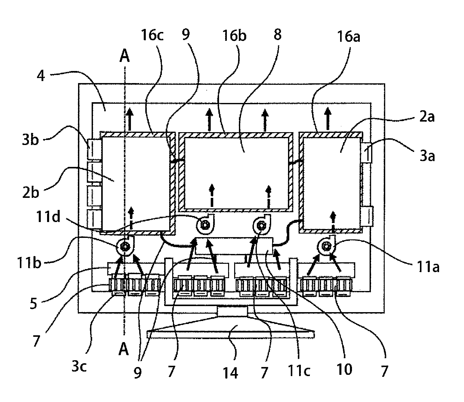
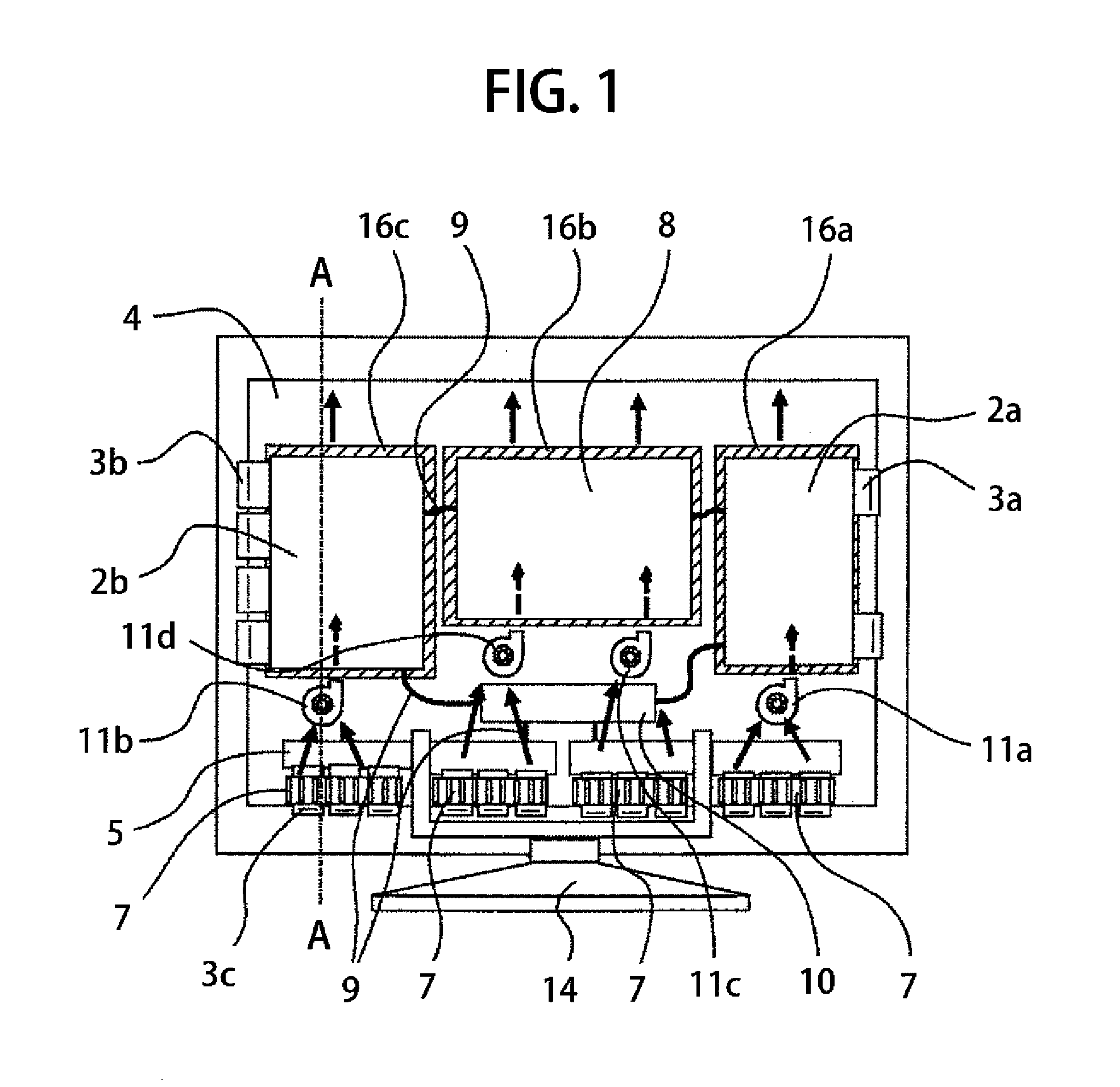
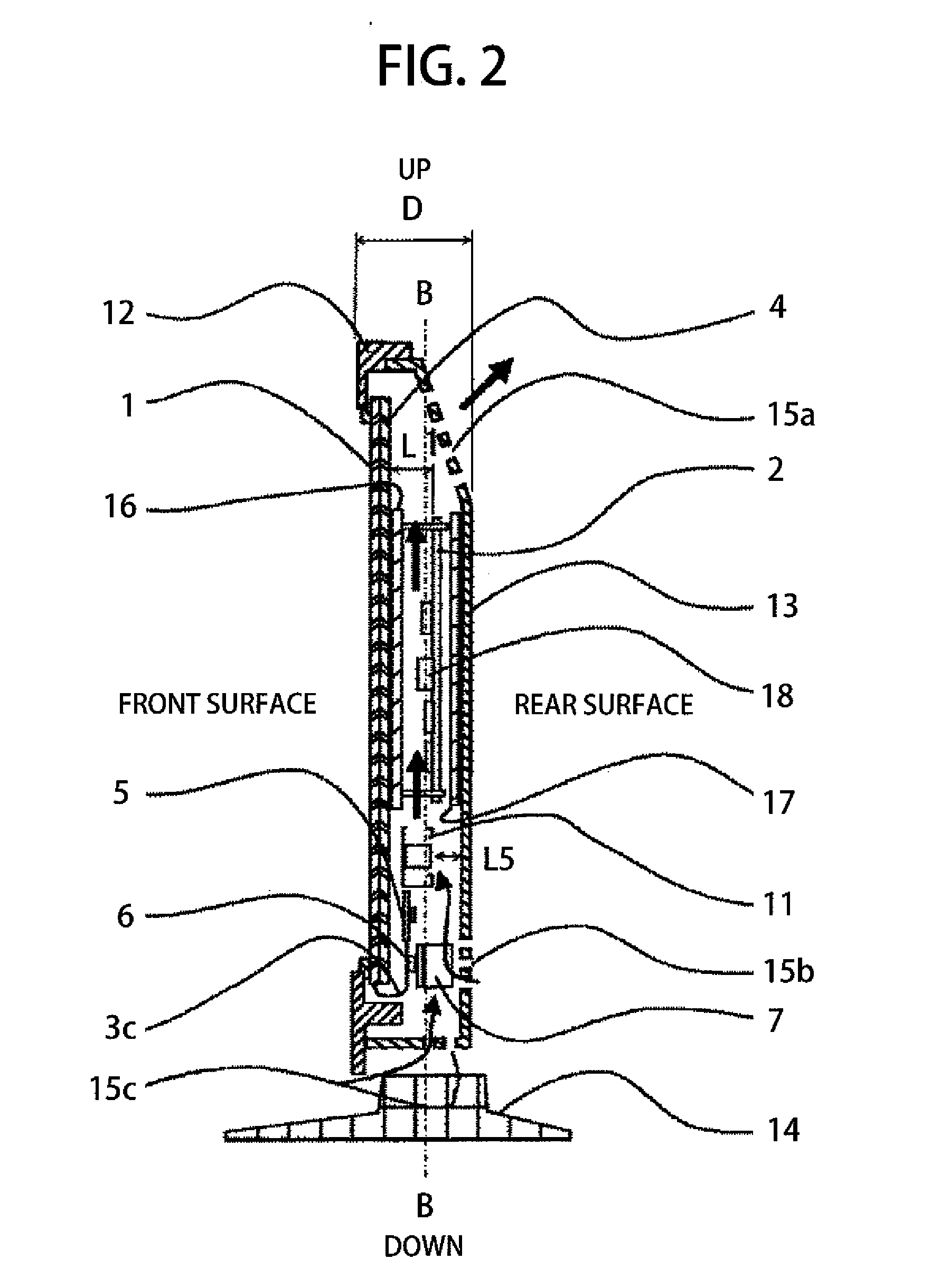
[0047]Herein, in the embodiment 1, as is shown in FIGS. 2 and 6, the display driver substrates 2a and 2b and the power source substrate 8 are installed in such direction that the circuit parts 18 on the display driver substrates 2a and 2b and the power source substrate 8 oppose to the chassis 4. The centrifugal fans 11a, 11b, 11c and 11d, directing the blow-off openings up in FIG. 2, are provided on the lower side of the display driver substrates 2a and 2b and the power source substrate 8. And, those centrifugal fans 11a, 11b, 11c and 11d ventilate the air into the gaps where the chassis 4 opposes to the display driver substrates 2a and 2b and the power source substrate 8. A gap distance “L5” between the main suction surfaces of the centrifugal fans 11a, 11b, 11c and 11d and the rear surface-side cover 13 comes to 10 to 15 mm, approximately. In case of the centrifugal fan, since the gap distance between the suction surface and the obstacle does not influence the flow rate, remarkabl...

embodiment 2

[0054]With the embodiment 2, as shown in FIGS. 15 and 16, among the circuit parts installed on the display driver substrates 2a and 2b, first insulator boards 16d, 16e and 16f are provided at the positions opposite to the positions of installing the circuit parts, each having height at least equal or greater than 50% of the height “H5” from the display driver substrates 2a and 2b (i.e., at least equal or greater than 50% with respect to the distance from the display driver substrate 2 up to the chassis 4).

[0055]FIG. 14 is the view for showing distribution of temperatures on the front surface of the display panel 1, corresponding to the structure according to the embodiment 1. Comparing to FIG. 9 of the result of the structure, which is thin-sized following the conventional structure, accompanying with changes in the structures of the fan 11 and the lower opening 15b, and the structure for installing the display driver substrates 2a and 2b and the power source substrate 8, the temper...

embodiment 3

[0059]The embodiment 3 has the structure of connecting the members 26a, 26b ad 26c of high thermal conductivity, between the insulator boards 16a, 16b and 16c, which are provided on the chassis 4, at portions corresponding to the positions opposite to the display driver substrates 2a and 2b, or the power source substrate 8, and the chassis 4. Thus, it is the structure of comprising the members, which are provided between the first insulator boards 16a, 16b and 16c and the chassis 4 and are high in the thermal conductivity in the in-plane direction thereof.

[0060]With such structure as was mentioned above, as well as maintaining the electric reliabilities thereof, but regarding the heat radiation or dissipation transferring from the display panel 1 to the chassis 4 through the thermal conductivity and dissipating into the housing, although such temperature distribution is generated as is shown in FIG. 14, because of being prevented by the adiabatic effect due to the first insulation m...


PUM


Abstract

A flat-type image display, such as, a plasma display, a LCD display, an OLED display, etc., in particular, for improving a cooling efficiency of a display panel, various kinds of substrates and an image display element, within the thin-sized housing thereof, comprises: a display panel; a chassis, which supports the display panel from a rear surface side thereof; a front surface-side cover, which is provided on a front side of the display panel; a rear surface-side cover, which is provided on a rear side of the display panel; an image display element connected with the display panel; a display driver substrate, which is connected with the display panel, and on a surface of which opposite to the chassis are provided circuit parts thereof; a power source substrate, which supplies driving power to the display driver substrate and the image display element, and on a surface of which opposite to the chassis are provided circuit parts thereof; and a first insulator board, which is provided at a position opposite to the display driver substrates and the power source substrate of the chassis.

Description

BACKGROUND OF THE INVENTION[0001]The present invention relates to an image display, and it relates to, in particular, cooling for display panels, such as, a plasma display, a LCD display, an OLED display, etc., for example, and / or various kinds of boards, and image processing elements thereof, as well.[0002]For a flat-type image display, such as, the plasma display and the liquid crystal display, etc., high-brightness and high-definition of images or pictures are required, and accompanying that, with an increase of a number of electronic parts for use of processing of images, further heat generation of the display panel and heat generation of various kinds of substrates are also increased, and therefore cooling for such heat generating parts comes to be a problem to be dissolved.[0003]A display for achieving dissolution of such problem accompanying with an increase of heat generation of the display panel module and the various kinds of substrates is already described in the followin...

Claims


Application Information

Patent Timeline
Patent Type & Authority Applications(United States)
IPC IPC(8): H05K7/20
CPCH05K7/20972
Inventor ISOSHIMA, NOBUYUKIMIYOSHI, KOHEIRI, MIKAYAMADA, YUTAKATSUTSUI, TOSHIHIROTANAKA, TEPPEIKUBOTA, HIDENAONISHINAKA, YUZO
Owner MAXELL HLDG LTD
Why Eureka
Try Eureka