Scroll compressor

a compressor and roller technology, applied in the direction of liquid fuel engines, machines/engines, rotary piston liquid engines, etc., to achieve the effect of reducing the noise of the pin-and-ring type self-rotation preventing mechanism, reducing the amount of self-rotation, and absorbing and easing the shock load operating on the pin

Active Publication Date: 2010-07-08
MITSUBISHI HEAVY IND LTD
View PDF7 Cites 23 Cited by
  • Summary
  • Abstract
  • Description
  • Claims
  • Application Information

AI Technical Summary

Benefits of technology

[0033]In accordance with Second Embodiment of the invention, the self rotation preventing ring of the pin-and-ring type self rotation preventing mechanism is provided through an elastic ring member fitted in an outer circumference of the self rotation preventing ring. Accordingly, the elastic ring member can absorb and ease the shock load operating on the pin and ring part by changing the orbit of the revolving scroll member at a point where the pin and ring part contributing to prevention of self rotation of the revolving scroll member is changed. This allows the noise (the shock sound) occurring in the pin-and-ring type self rotation preventing mechanism to be reduced.
[0034]In accordance with the invention, a change of the orbit of the center of the ring hole (the orbit bending angle ξ) in a change of the self rotation preventing pin can be smoothed and a shock load given to the pin and ring part in accordance with a change in speed due to the above to be reduced. This allows the noise (the shock sound) occurring in the pin-and-ring type self rotation preventing mechanism to be suppressed. Moreover, a decrease of the maximum displacement R in a direction of self rotation of the revolving scroll member can reduce an amount of self rotation (a twist amount) of the revolving scroll member. This allows a leakage of gas due to a twist of the revolving scroll member to be reduced and a performance in compression to be improved.
[0035]Further, in accordance with the invention, the elastic ring member can absorb and ease the shock load operating on the pin and ring part in accordance with a change of the orbit of the center of the ring hole at a point where the pin and the ring, which contribute to prevention of self rotation of the revolving scroll member, are changed. This allows the noise (the shock sound) occurring in the pin-and-ring type self rotation preventing mechanism to be reduced.

Problems solved by technology

This can be considered to be a cause of a noise (a shock sound) occurring in the pin-and-ring type self rotation preventing mechanism.

Method used


Image

  • Scroll compressor
  • Scroll compressor
  • Scroll compressor

Examples


first embodiment

[0076]Now, described will be First Embodiment of the invention with reference to FIGS. 1 to 8.

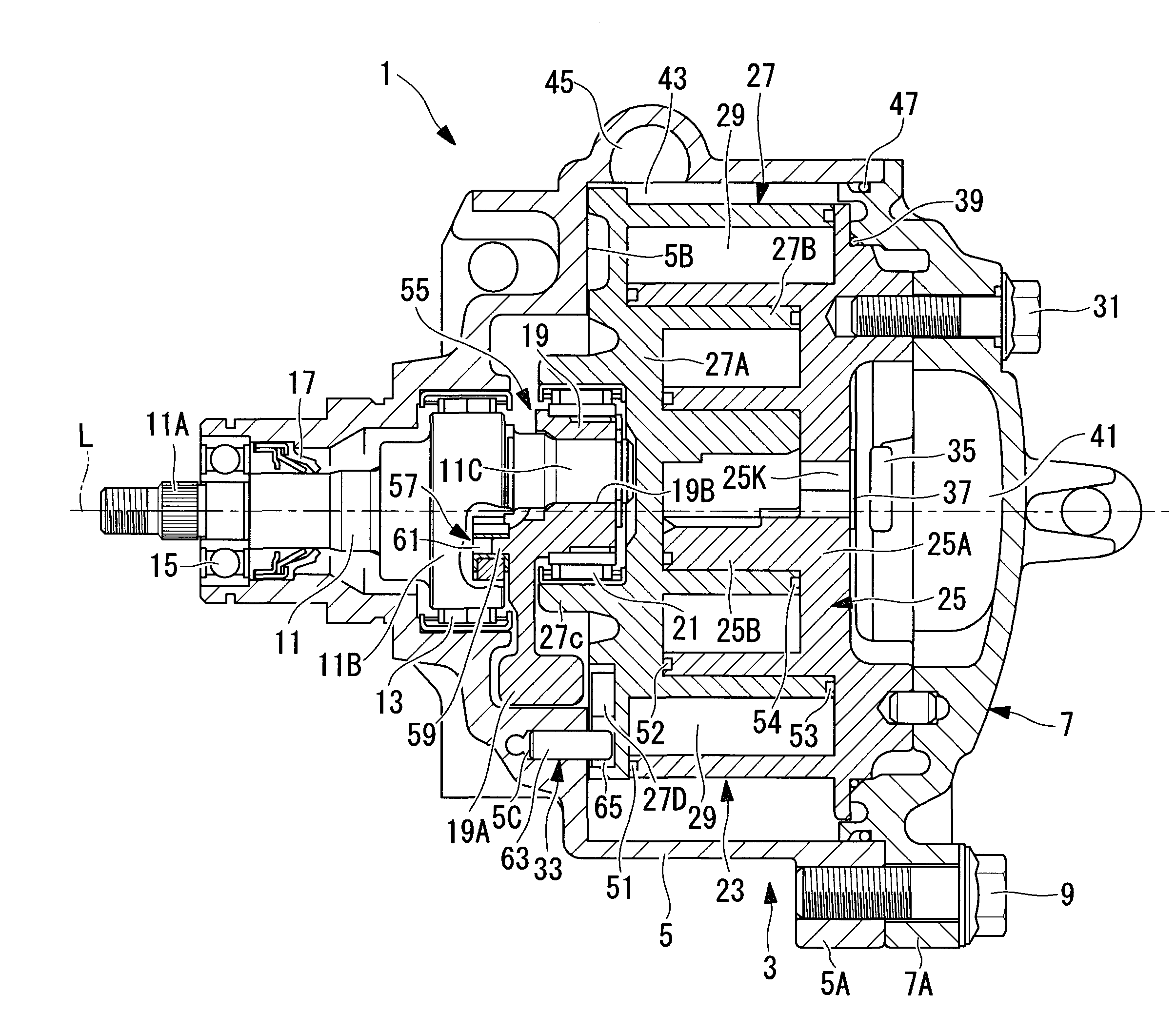
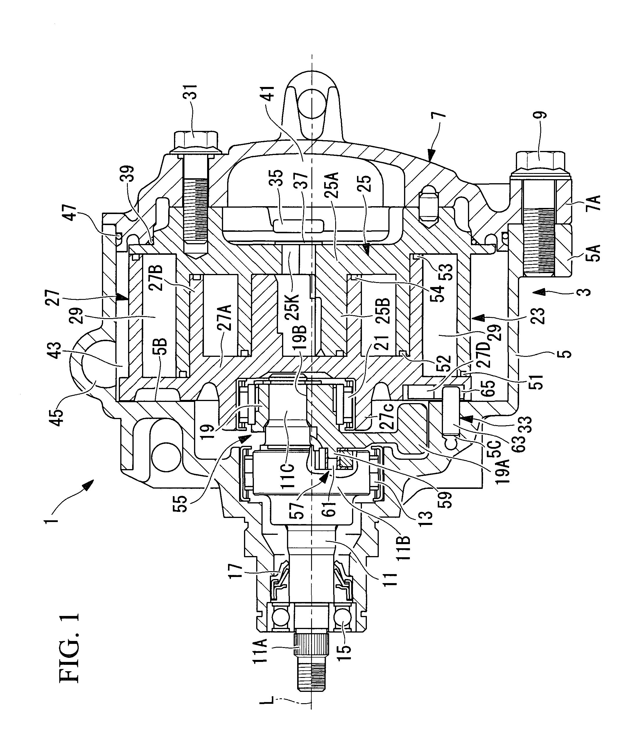
[0077]FIG. 1 is a vertically sectional view of a scroll compressor 1 in accordance with First Embodiment of the invention. The scroll compressor 1 includes a housing 3 forming a substantially outer shape of the scroll compressor 1. The housing 3 is formed from a front housing 5 and a rear housing 7, which are fastened by means of a bolt 9 into one body. In respective circumferentially plural places, four places, for example, of the front housing 5 and the rear housing 7, formed into one body at even intervals are flanges 5A and 7A for fastening. Fastening the flanges 5A and 7A by means of the bolt 9 allows the front housing 5 and the rear housing 7 to be united into one body.

[0078]In the front housing 5, a crank shaft (a drive shaft) 11 is supported around an axial L through main bearings 13 and sub bearings 15 so as to be freely rotatable. One end of the crank shaft 11 (on the left side in...

second embodiment

[0110]Now, described will be Second Embodiment of the invention, made reference to FIG. 9.

[0111]Second Embodiment is different from First Embodiment in a part of the shape of the orbit correction part 67 provided in the ring hole 27D of the revolving scroll member 27. Other points are same as First Embodiment, and therefore, omitted from description.

[0112]In Second Embodiment, the orbit correction part 67 is arranged to form the shape of a ring hole formed by extending the small arc 67A having the small center distance R at least to the point S (θ=45 deg) at which the pin and the ring is changed, further extending the extended arc a little for the purpose of absorbing tolerances of a location for providing the self rotation preventing pin 63 and such, and then, connecting the extended arc to the ring hole 27D of the large arc 67B having the large center distance R through a connection part 67D.

[0113]Forming the ring hole 27D of the revolving scroll member 27 into the above shape als...

third embodiment

[0115]Now, described will be Third Embodiment of the invention, made reference to FIG. 10.

[0116]Third Embodiment is different from First Embodiment in a structure of the self rotation preventing ring 65. Other points are same as First Embodiment, and therefore, omitted from description.

[0117]In Third Embodiment, an orbit correction part 97 is provided in the self rotation preventing ring 65 so that the ring hole 27D provided in the revolving scroll member 27 would be formed into the shape of a complete circle, an outer circumference of the self rotation preventing ring 65 fitted to the ring hole 27D would be formed into the shape of a complete circle and the ring thickness, which is a difference between an outer diameter and an inner diameter, would be increased by ΔR in a section of prevention of self rotation. The shape of an inner circumference of the self rotation preventing ring 65 in Third Embodiment is similar to the shape of the ring hole 27D described in First Embodiment. T...


PUM


Abstract

To provide a scroll compressor capable of reducing a noise occurring in a pin-and-ring type self rotation preventing mechanism and improving compression performance. In a scroll compressor comprising: a fixed scroll member and a revolving scroll member; a driven crank mechanism for driving the revolving scroll member to revolutionary turn; and a pin-and-ring type self rotation preventing mechanism provided in plural places for preventing self rotation of a revolving scroll member, at least one of the self rotation preventing pin, the self rotation preventing ring and the self rotation preventing ring hole, which form the pin-and-ring type self rotation preventing mechanism, is provided with an orbit correction part for reducing a maximum displacement R in a direction of self rotation of the revolving scroll member to smooth a change of an orbit of the revolving scroll member in changing a pin and a ring in a section of prevention of self rotation by means of a corresponding pin and ring part.

Description

TECHNICAL FIELD[0001]The invention relates to a scroll compressor comprising a driven crank mechanism for making a revolving radius of a revolving scroll member variable and a pin-and-ring type self rotation preventing mechanism for preventing self rotation of the revolving scroll member.BACKGROUND ART[0002]In a scroll compressor comprising a pair of a fixed scroll member and a revolving scroll member, which are engaged with each other to form a compression chamber, even in the case that the fixed scroll member and the revolving scroll member have a fine process error or an assembly error, conventionally used has been a driven crank mechanism for certainly making laps contact with each other to minimize a leakage of compression gas so as to secure compression efficiency in accordance with the error. The driven crank mechanism is arranged to be able to make a revolving radius of the revolving scroll member variable. The driven crank mechanism uses centrifugal force, compression react...

Claims


Application Information

Patent Timeline
Patent Type & Authority Applications(United States)
IPC IPC(8): F04C18/02
CPCF01C17/063F04C18/0215F04C2270/13F04C18/0276F04C18/0253
Inventor KUWAHARA, TAKAYUKIUKAI, TETSUZOUFUJITA, KATSUHIROITO, TAKAHIDETAKEUCHI, MAKOTOHIOKI, NORIOHAMAMURA, HIDESHITERASAKI, KOJI
Owner MITSUBISHI HEAVY IND LTD
Why Eureka
Try Eureka