Low inductance connector assembly

Inactive Publication Date: 2010-07-08
GM GLOBAL TECH OPERATIONS LLC
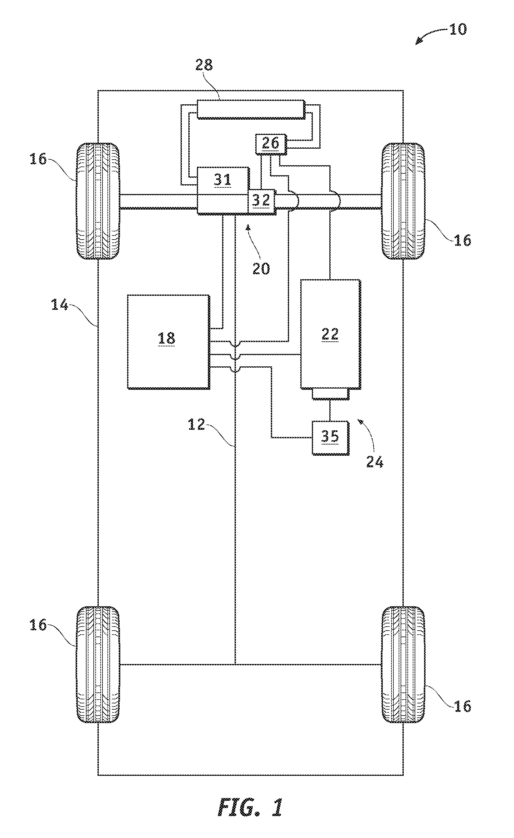
View PDF3 Cites 12 Cited by
  • Summary
  • Abstract
  • Description
  • Claims
  • Application Information

AI Technical Summary

Problems solved by technology

Such busbar systems often involve two or more intricately designed laminar positive and negative electrodes that overlap for most of the area of the busbar.
Moreover, some conventional inverters have been observed to incur voltage spikes when currents flowing through the power module abruptly change, such as when the inverter is switched on or off.
That is, even relatively small changes in current can produce relatively large voltage spikes if the inductance is high.

Method used


Image

  • Low inductance connector assembly
  • Low inductance connector assembly
  • Low inductance connector assembly

Examples


Embodiment Construction

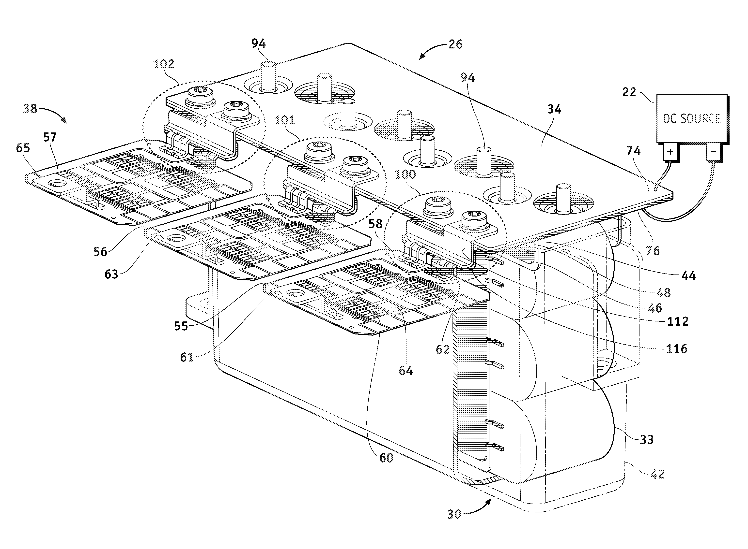
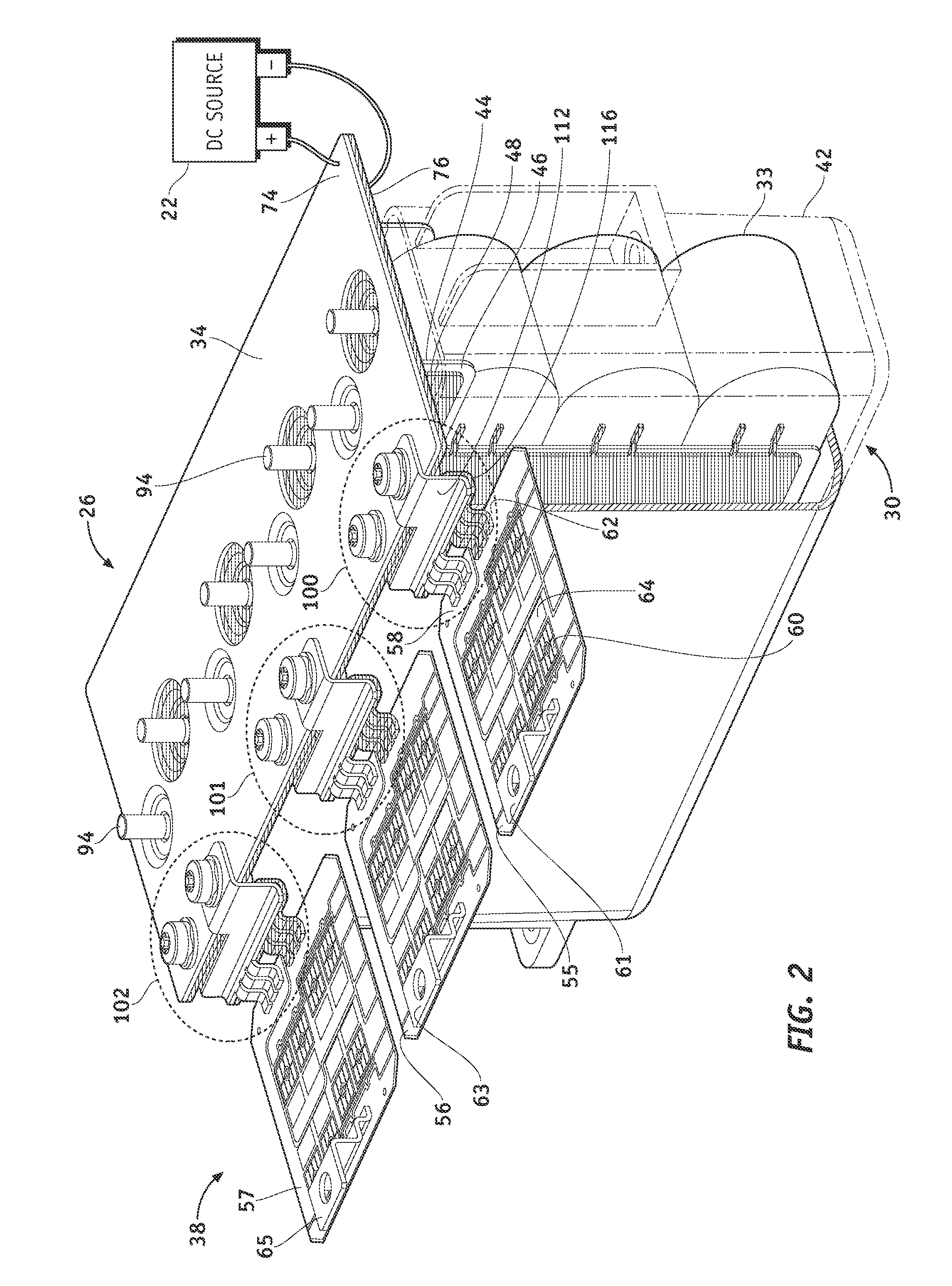
[0014]The various embodiments of the present invention described herein provide a connector assembly for a busbar system having a reduced inductance. The connector assembly includes two overlapping, conductive, and electrically isolated bridge electrodes, each electrode configured to electrically couple a positive or negative electrode of a primary busbar assembly with a power module input contact. Each bridge electrode forms a conductive pathway between these points that substantially overlaps and crosses with the pathway formed by the other bridge electrode. Further, each bridge electrode is configured with a connecting tab that overlaps with both positive and negative electrodes of the primary busbar assembly in the region where the tab is fastened. The contribution to busbar system inductance from the connector assembly is reduced as a result of the increased area of overlap of the primary busbar and bridge electrodes and the crossed current pathways this configuration provides....


PUM


Abstract

A busbar connector assembly for coupling first and second terminals on a two-terminal device to first and second contacts on a power module is provided. The first terminal resides proximate the first contact and the second terminal resides proximate the second contact. The assembly comprises a first bridge having a first end configured to be electrically coupled to the first terminal, and a second end configured to be electrically coupled to the second contact, and a second bridge substantially overlapping the first bridge and having a first end electrically coupled to the first contact, and a second end electrically coupled to the second terminal.

Description

STATEMENT REGARDING FEDERALLY SPONSORED RESEARCH OR DEVELOPMENT[0001]This invention was made with Government support under DE-FC26-07NT43123 awarded by US-Department of Energy. The Government has certain rights in this invention.TECHNICAL FIELD[0002]The present invention generally relates to automotive busbar systems, and more particularly relates to low inductance connector assemblies for an automotive busbar system.BACKGROUND OF THE INVENTION[0003]Electric and hybrid electric vehicles often use sources of high voltage such as battery packs or fuel cells that deliver direct current (DC) to drive vehicle motors, electric traction systems, and other vehicle systems. These systems typically include power inverters to convert DC input from the power source to a 3-phase alternating current (AC) output compatible with electric motors and other electrical components. Such inverters generally include both power and capacitor modules interconnected by a busbar system that distributes curren...

Claims


Application Information

Patent Timeline
IPC IPC(8): H01R4/60
CPCB60R25/00H05K7/14329
Inventor HOLBROOK, MEGHAN ANNCARLSON, DOUGLAS S.
Owner GM GLOBAL TECH OPERATIONS LLC
Why Eureka
Try Eureka