
Printing method and display apparatus manufacturing method

Inactive Publication Date: 2010-07-08
SONY CORP
View PDF8 Cites 16 Cited by
  • Summary
  • Abstract
  • Description
  • Claims
  • Application Information

AI Technical Summary

Benefits of technology

[0006]In Japanese Patent No. 3689536, a method for accurately printing a resin such as a resist material by using a reverse offset printing method is proposed. Specifically, by using a resin for a color filter as an ink, a print pattern having a thickness of 0.8 μm is obtained. Although the resolution of the print pattern is not described in detail, it is expected that the target line width is at least about 50 μm because the color filter is for a liquid crystal display. In Japanese Patent No. 3689536, since there is a description “It shows that printing a line having a width of 10 μm is possible.”, the dimensional limit of this printing method is estimated to be about 10 μm.
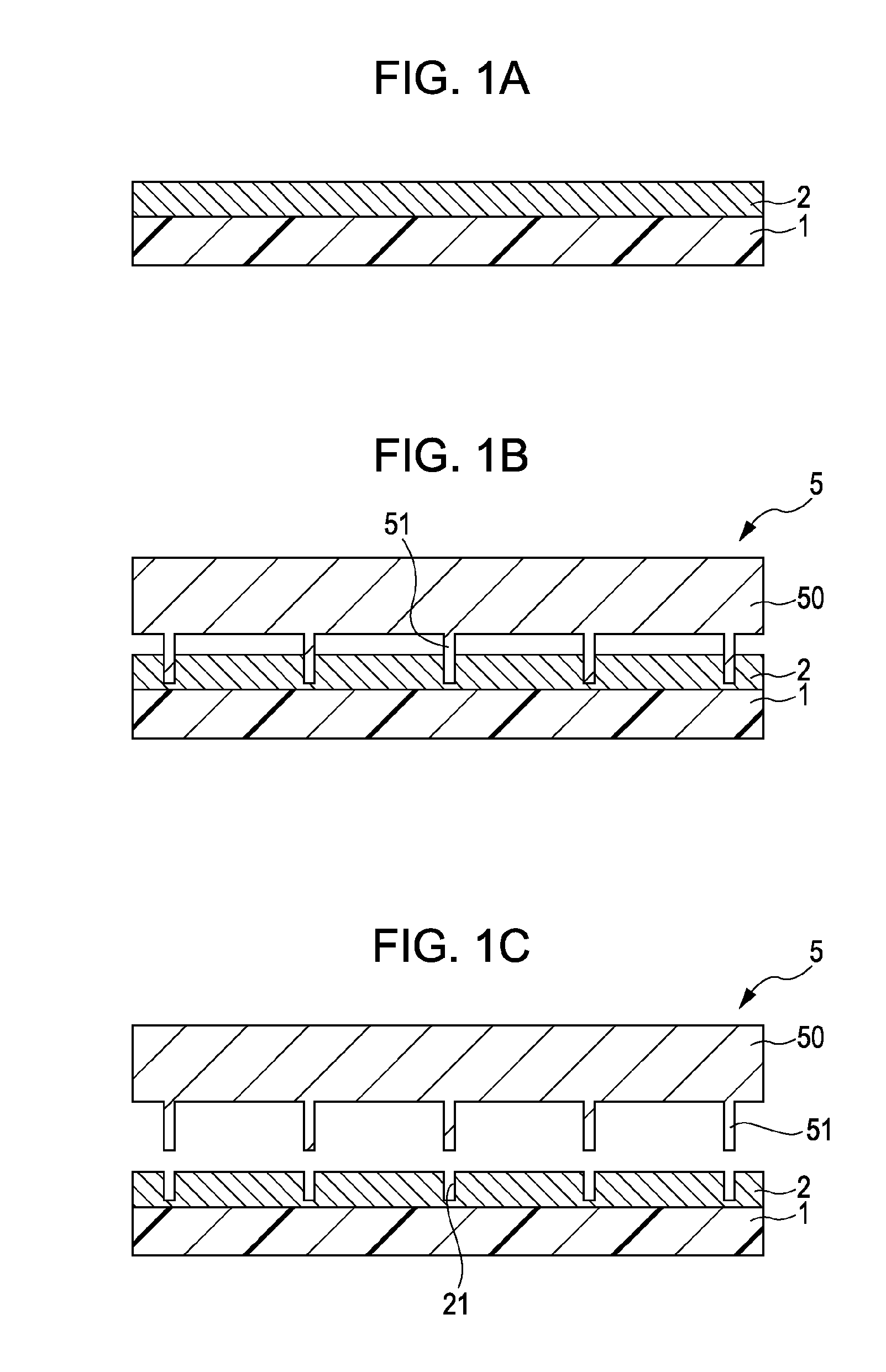
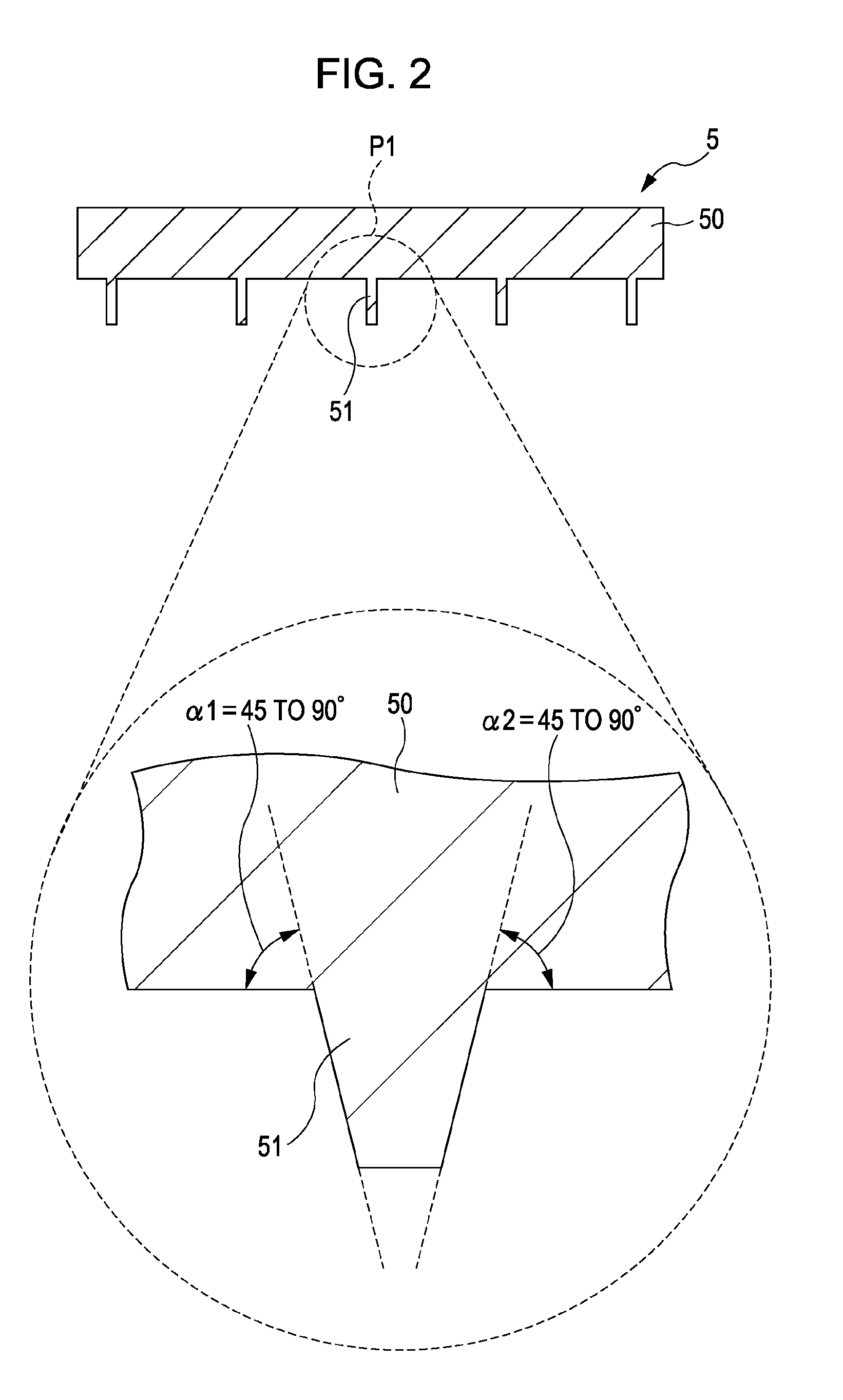
[0012]In the printing method and the display apparatus manufacturing method according to an embodiment of the present invention, the protrusion portion of the mold member is pressed against the transfer layer on the blanket, so that the groove portion having the pattern corresponding to the protrusion portion is formed on the transfer layer (molding process). Thereafter, by causing the transfer layer on the blanket and the relief printing plate including the convex portion to face each other and pressure-contacting them, a portion corresponding to the convex portion on the transfer layer is selectively eliminated and the print pattern layer is formed on the blanket (first transfer process). Thereafter, by causing the print pattern layer on the blanket and the substrate to be printed to face each other and pressure-contacting them, the print pattern layer is transferred onto the substrate to be printed (second transfer process). In this way, the groove portion is formed on the transfer layer by using the mold member, and thereafter the first transfer process is performed by using the relief printing plate, so that, even when the film thickness of the transfer layer (print pattern layer) is large, the portion corresponding to the convex portion on the transfer layer can be sheared easier than the related art.
[0013]According to the printing method and the display apparatus manufacturing method of an embodiment of the present invention, the groove portion having a pattern corresponding to the protrusion portion is formed on the transfer layer by pressing the protrusion portion of the mold member against the transfer layer on the blanket, and thereafter, the portion corresponding to the convex portion in the transfer layer is selectively eliminated and the print pattern layer is formed on the blanket by causing the transfer layer on the blanket and the relief printing plate including the convex portion to face each other and pressure-contacting them, so that the portion corresponding to the convex portion on the transfer layer can be easily sheared even when the thickness of the transfer layer (print pattern layer) is large. Therefore, a print sharper than that in the related art can be performed independent of the film thickness of the print pattern.

Problems solved by technology

As described above, in the related art, when printing an ink constituted by a resin, an organic solvent, and the like, there is a problem that the sharpness of the print pattern decreases as the film thickness increases.

Method used


Image

  • Printing method and display apparatus manufacturing method
  • Printing method and display apparatus manufacturing method
  • Printing method and display apparatus manufacturing method

Examples


embodiment

1. Embodiment

Process Example of a Printing Method Using a Mold

[0031]FIGS. 1 to 5 are cross sectional-views for explaining a printing method according to an embodiment of the present invention.

(Transfer Layer Forming Process (Coating Process))

[0032]First, as shown in FIG. 1A, by coating an ink 2 on a flat plate blanket 1, a transfer layer constituted by the ink 2 is formed on the flat plate blanket 1.

[0033]The flat plate blanket 1 has to be able to be transformed flexibly in order to realize a good contact with a substrate to be printed (substrate 4) described below. Therefore, as a mechanical property of the flat plate blanket 1, the Young's modulus is preferably about 0.01 to 10 MPa. In view of the coating property and peeling property of the ink 2, the surface tension of the flat plate blanket 1 is preferably 15 to 40 dyn / cm. As a material satisfying the above properties, a silicone rubber, a fluorine resin, or the like can be used as a material of the flat plate blanket 1.

[0034]A...

application example

3. Modified Example and Application Example

[0060]Although, the present invention has been described using the embodiment and the example, the present invention is not limited to the embodiment or the like, and various modifications are possible.

[0061]For example, although, in the embodiment or the like, a case has been described in which the groove portion 21 formed on the ink 2 has a concave shape, for example, as shown in FIG. 9, the groove portion 21 penetrating to the surface of the flat plate blanket 1 may be formed. When the groove portion 21 penetrates to the surface as described above, for example, as shown in FIG. 10, a portion corresponding to the convex portion 31 in the ink 2 can be sheared more easily. The print pattern 2A formed in this case has, for example, a cross sectional shape as shown in FIG. 11.

[0062]Although, the above embodiment or the like has been described using the flat plate blanket as an example of the blanket, a blanket having another shape (for exampl...


PUM

PropertyMeasurementUnit
Angleaaaaaaaaaa
Angleaaaaaaaaaa
Surface tensionaaaaaaaaaa

Abstract

A printing method including the steps of, forming a transfer layer on a blanket, forming a groove portion on the transfer layer by pressing a protrusion portion of a mold member including the protrusion portion having a predetermined pattern against the transfer layer, the groove portion having the pattern corresponding to the protrusion portion, forming a print pattern layer on the blanket by causing the transfer layer on the blanket and a relief printing plate including a convex portion having a pattern corresponding to a reverse pattern of the protrusion portion to face each other and pressure-contacting them so that a portion on the transfer layer corresponding to the convex portion is selectively eliminated, and transferring the print pattern layer onto a substrate to be printed by causing the print pattern layer on the blanket and the substrate to be printed to face each other and pressure-contacting them.

Description

BACKGROUND OF THE INVENTION[0001]1. Field of the Invention[0002]The present invention relates to a printing method using a blanket and a relief printing plate, and a display apparatus manufacturing method using such a printing method.[0003]2. Description of the Related Art[0004]In recent years, a technical field called “printable electronics” has been significantly developed. An object of printable electronics is to manufacture expensive electronic components, which have been produced so far by fully using semiconductor manufacturing techniques, at low cost by using a printing method and a nanoimprint method. Another object is to provide a flexible device by replacing a substrate with a film.[0005]Therefore, in the related art, various printing methods have been proposed (for example, Japanese Patent No. 3689536 and a non-patent document, Youn-Gyoung, et al. “Design Parameters of Roll Printing Process for TFT-LCD Fabrication”, SID08GIGEST, p. 637-640, 2008)SUMMARY OF THE INVENTION[0...

Claims


Application Information

Patent Timeline
IPC IPC(8): B41F1/16H01J9/00
CPCB82Y10/00H01L27/1288G03F7/0002B82Y40/00H05K3/1275
Inventor TANAKA, MASANOBUKAMEI, TAKAHIRO
Owner SONY CORP
Learn More