
Multiple lumen diffusion catheter

Inactive Publication Date: 2010-07-08
BAYER HEALTHCARE LLC
View PDF18 Cites 12 Cited by
  • Summary
  • Abstract
  • Description
  • Claims
  • Application Information

AI Technical Summary

Benefits of technology

[0009]The present invention overcomes many of the problems in the art by providing a catheter tip that is self-centering within a lumen and includes a plurality of discharge hole sets that are constructed and arranged to create bolus clouds, rather than a single jet bolus, of injectate. The bolus clouds, in contradistinction to an injectate stream from an end port of a catheter, are concentrated masses of injectate that maximize imaging while minimizing the amount of injectate necessary, providing atraumatic vascular injection. The cloud configuration concentrates contrast agent around the catheter, a phenomenon that does not occur with end hole injection since the jet distributes contrast linearly along the vessel. The holes may be deployed according to a spatial / longitudinal gradient down the catheter to provide equal injection of contrast (or other injectate) volume per unit of catheter length. Hence, a bolus concentrator is formed as all exiting contrast in cloud form displaces blood retrograde and antegrade at the injection site. By controlling flow rate through the injection catheter, any bolus spatial length and concentration can be achieved. Such bolus concentration-time control is not obtainable using end-hole devices. The plurality of holes also permits excellent blood-agent mixing, if desired. The smaller nature of the holes create a pressure gradient that uses energy from the flowing injectate, and thus by decreasing energy causes less likelihood of injuring tissue, or whipping of the catheter.
[0010]Control over bolus length, concentration, and movement in retrograde and antegrade directions is significantly enhanced by providing catheters having multiple lumens and corresponding hole sets through which fluid exits the lumens. Hole sets emitting a non-agent fluid such as saline are used to influence the bolus cloud of holes emitting an agent. The saline hole sets may have different hydraulic impedance than the agent hole sets to allow differential fluid exit pressure from the saline hole sets compared to the agent hole sets.
[0011]Moreover, saline hole sets may be provided on either side of an agent hole set, so that pressure may be enhanced preferentially at either end of the agent hole set, thus keeping the agent bolus focused. Either of the saline clouds emitted from the saline hole sets may be diminished relative to the other such that the agent bolus is “pushed” in one direction or the other.
[0014]In a related aspect, the invention provides a method of preventing retrograde flow. The method includes the steps of: introducing a first fluid into a lumen through which a native fluid is flowing; and introducing a second fluid upstream of the first fluid such that the first fluid is prevented from traveling upstream by the second fluid.

Problems solved by technology

Such bolus concentration-time control is not obtainable using end-hole devices.

Method used


Image

  • Multiple lumen diffusion catheter
  • Multiple lumen diffusion catheter
  • Multiple lumen diffusion catheter

Examples


Embodiment Construction

Multiple Lumen Design

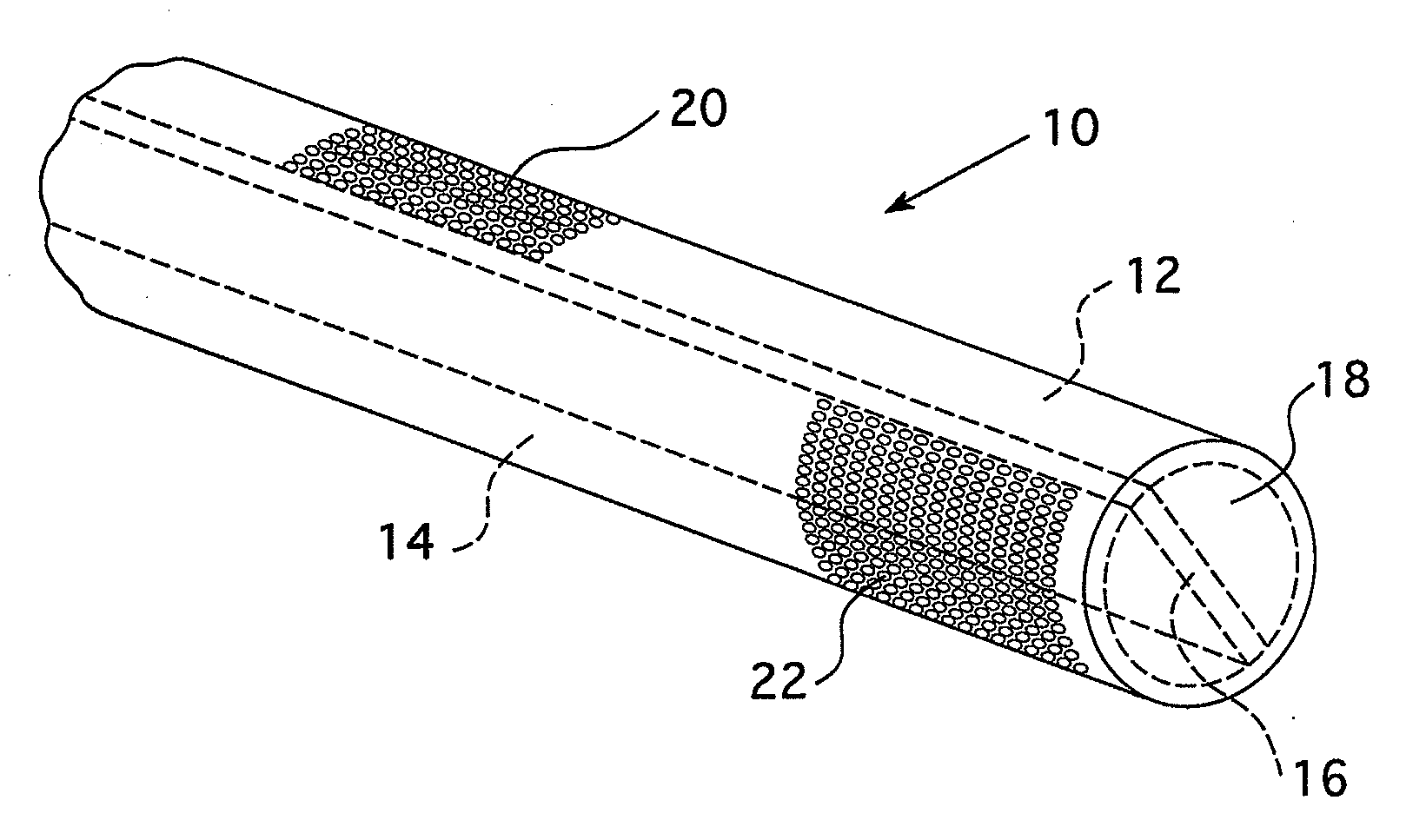
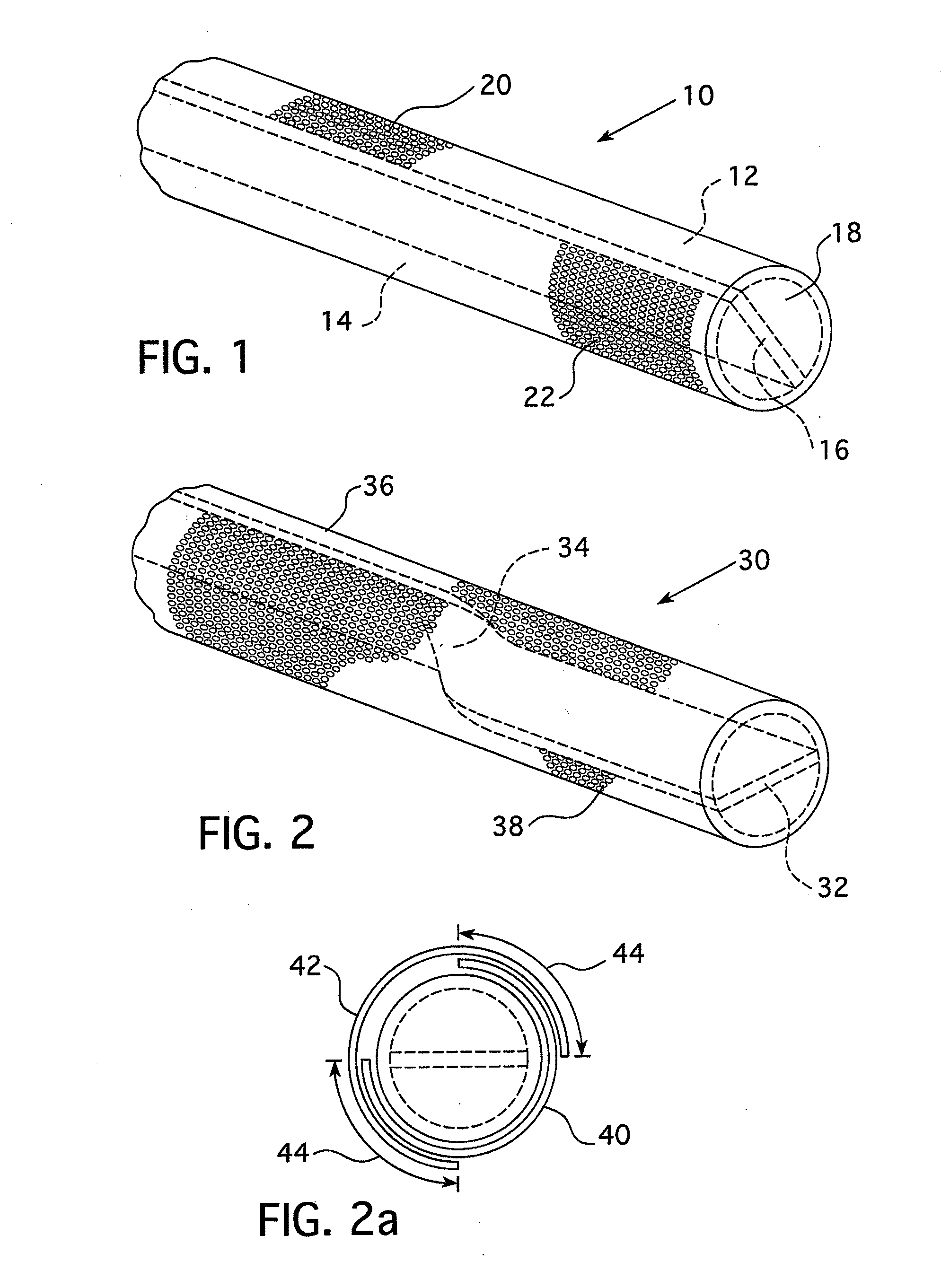
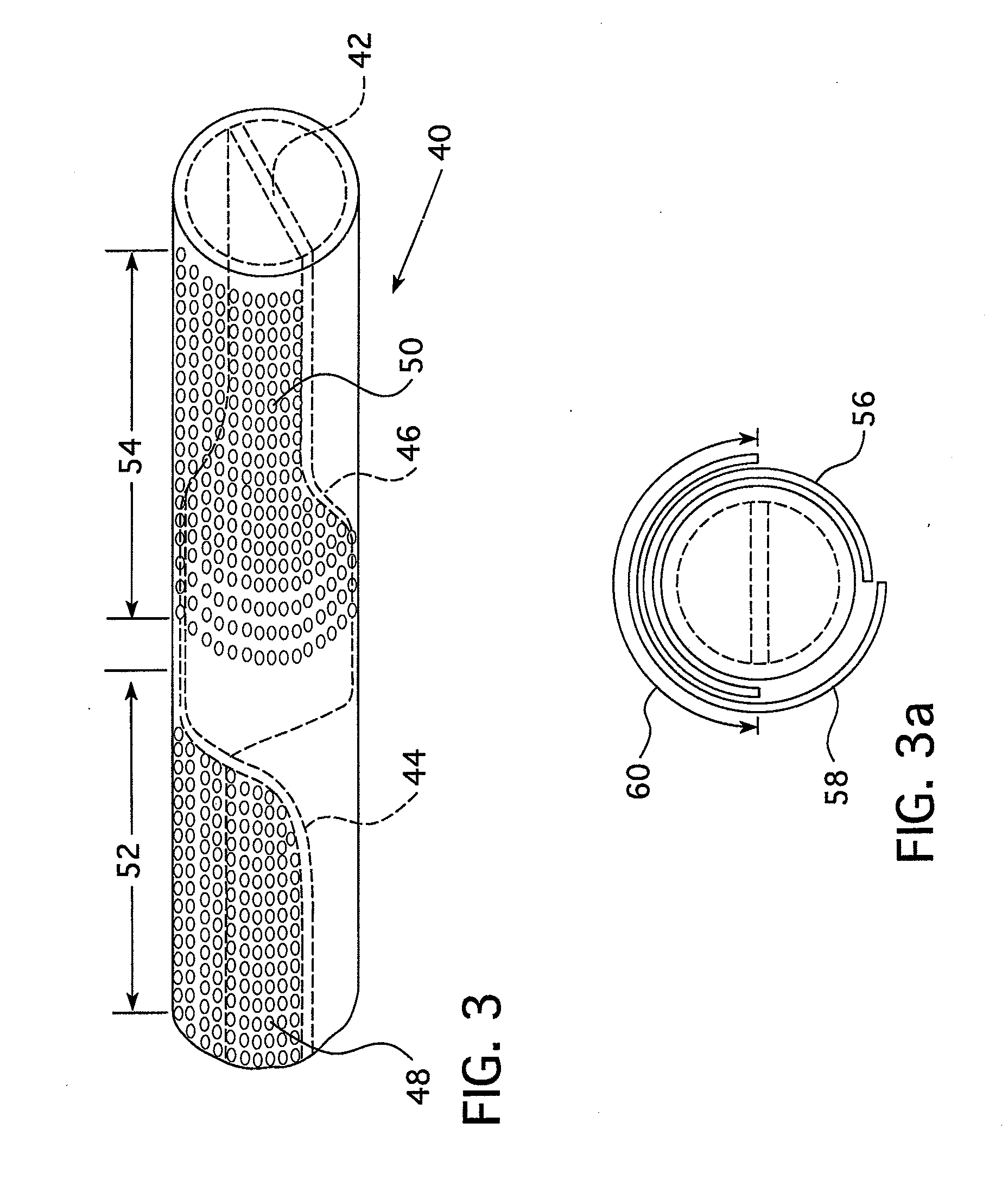
[0034]The various embodiments of the present invention include many innovative characteristics, each of which will be described in detail herein with the understanding that each of these characteristics may be used in combination with any or several of the other characteristics without departing from the spirit of the present invention. As such, one characteristic common to each of the various embodiments of the present invention is a multiple lumen design. For example, FIG. 1 shows an embodiment of a catheter 10 having a first lumen 12 and a second lumen 14. The catheter 10 may be a guiding catheter, microcatheter, balloon catheter, injection catheter, or any other catheter. The lumina 12 and 14 are separated by a baffle 16 that runs longitudinally through the center of the catheter 10, bifurcating the interior space of the catheter into the two lumina 12 and 14. The distal end 18 of the catheter 10 is preferably blocked, but may have a small hole to accommodat...


PUM


Abstract

A method and device for the simultaneous or sequential introduction of multiple fluids into the bloodstream including a multiple lumen catheter with corresponding multiple hole sets. By introducing a second fluid such as saline, the concentration and bolus of a first fluid, such as a contrast agent, can be controlled and optimized.

Description

RELATED APPLICATIONS[0001]This application claims priority to U.S. Application Ser. No. 60 / 867,550, entitled MULTIPLE LUMEN DIFFUSION CATHETER, filed on Nov. 28, 2006 by Schwartz, et al., the entirety of which is incorporated herein by reference.FIELD OF THE INVENTION[0002]The present invention relates to a specialized catheter for insertion into an artery, vein, or other body structure, with principal use for contrast injection during an X-Ray, MRI, CT, CTA or other imaging or therapeutic procedure. Because it may be made for arterial application, or because of its arterial or venous concentrating capability, the catheter of the invention decreases contrast dose, making it ideal for use in treatment or diagnosis of diabetic renal disease or other renal dysfunction that mandates reduction in the dosage of contrast.BACKGROUND OF THE INVENTION[0003]Internal imaging is often enhanced through the use of injected imaging agents that allow an imaging technique (MRI, CTA, x-ray, ultrasound...

Claims


Application Information

Patent Timeline
IPC IPC(8): A61B6/00A61M25/00
CPCA61M25/007A61M25/003
Inventor SCHWARTZ, ROBERT S.VAN TASSEL, ROBERT A.GELBLUM, EUGENE A.HIRSCHMAN, ALAN D.KALAFUT, JOHN F.REILLY, DAVID M.RHINEHART, EDWARD J.TROMBLEY, III, FREDERICK W.UBER, III, ARTHUR E.
Owner BAYER HEALTHCARE LLC
Learn More