Ultrasound 3D imaging system

a technology of ultrasound and imaging system, applied in the field of ultrasound medical imaging system, can solve problems such as image quality compromis

Active Publication Date: 2010-07-08
TERATECH CORP
View PDF108 Cites 71 Cited by
  • Summary
  • Abstract
  • Description
  • Claims
  • Application Information

AI Technical Summary

Benefits of technology

[0007]A preferred embodiment of the invention employs a sparse array where only a fraction of the transducer elements need to be activated. By selecting the four corner elements of the array to provide proper mean lobe bandwidth, minimizing average sidelobe energy and clutter, eliminating periodicity and maximizing peak to side lobe ratio, quality images are produced. To steer the beams across the volume or region of interest, different transducer elements must be actuated in proper sequence to maintain the peak to sidelobe ratio. The system processor can be programmed to provide the desired sequence for transducer actuation to direct the beam at different angles. Alternatively, a discrete controller can be used to control sparse array actuation. A preferred embodiment provides a scan head with integrated switching circuits for sequentially selecting sparse array actuation elements for sequential multiple beamforming. The scan head can be connected to a conventional ultrasound system in which the scan head provides the inputs to the conventional beamforming processing functions. In another embodiment, the transmit array elements and receive array elements can be operated independently with the transmit elements comprising a sparse array and the receive elements being a near fully populated array. In a preferred embodiment, the multiplexer and beamformer circuits can be integrated into an interface system, or alternatively, into a host processing system, leaving a 2D transducer array mounted in the probe housing.
[0009]Using high voltage multiplexers in the probe and the nondestructive sensing allows for time multiplexed sequential beamforming. It is now possible to sequentially change tap selection of each delay line to form multiple beams.
[0013]A preferred embodiment of the invention performs real time imaging of large volumes such as the human heart without having to take gated images of different portions of the heart in sequence and then stitch the images together. This can be done using beamforming architectures in which multiple beams can be transmitted in a single pulse. This can be done with a narrowband phase shifting beamforming system and / or with a time domain beamforming system. By using parallel and serial beamforming components distributed in the transducer probe housing and the system main processor housing lightweight portable and cart mounted systems can be used for real time full volume cardiac imaging.

Problems solved by technology

The power required to operate such systems has resulted in the use of an analog phase shift technique with a digital delay beamformer that results in a compromise of image quality.

Method used


Image

  • Ultrasound 3D imaging system
  • Ultrasound 3D imaging system
  • Ultrasound 3D imaging system

Examples


Embodiment Construction

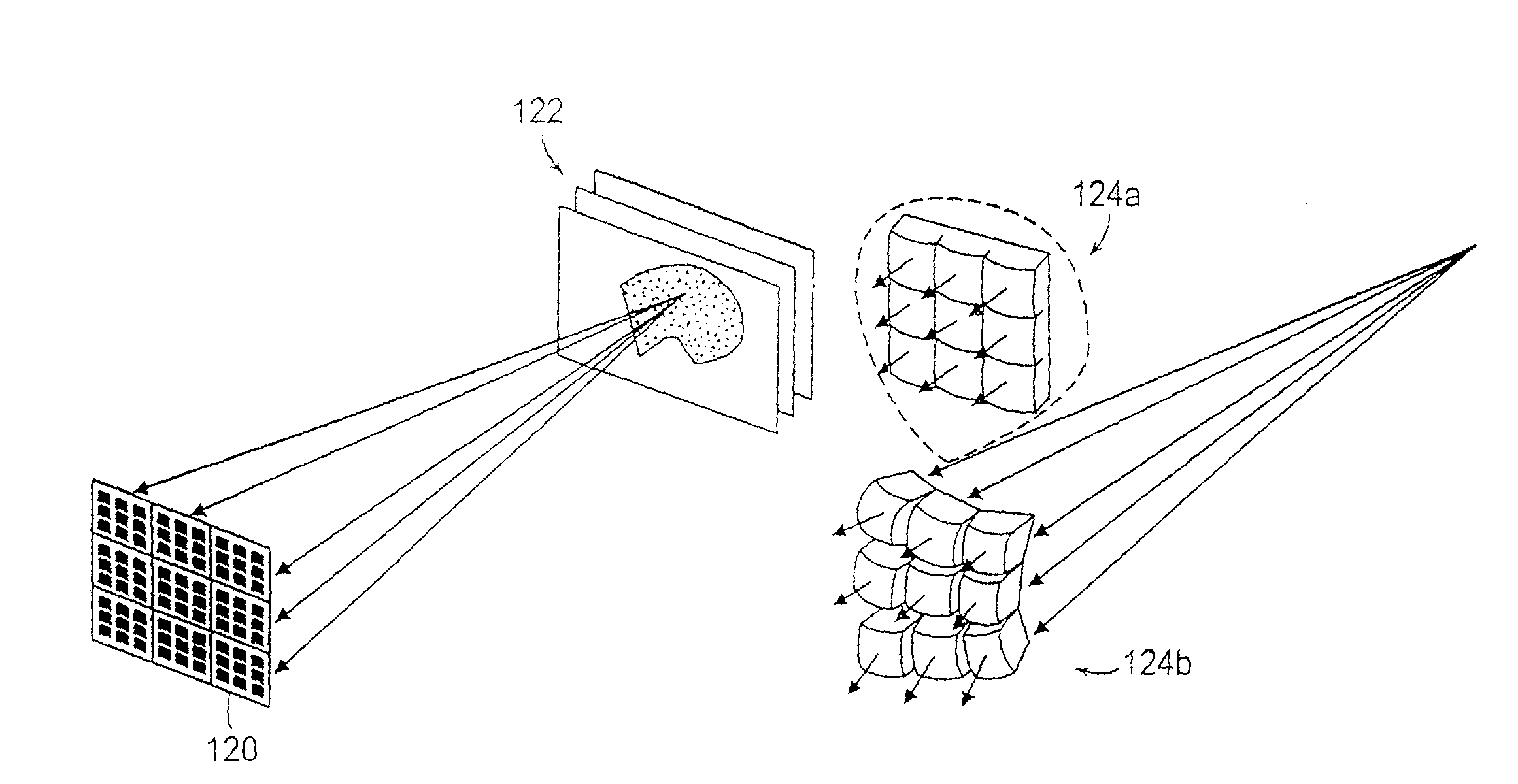
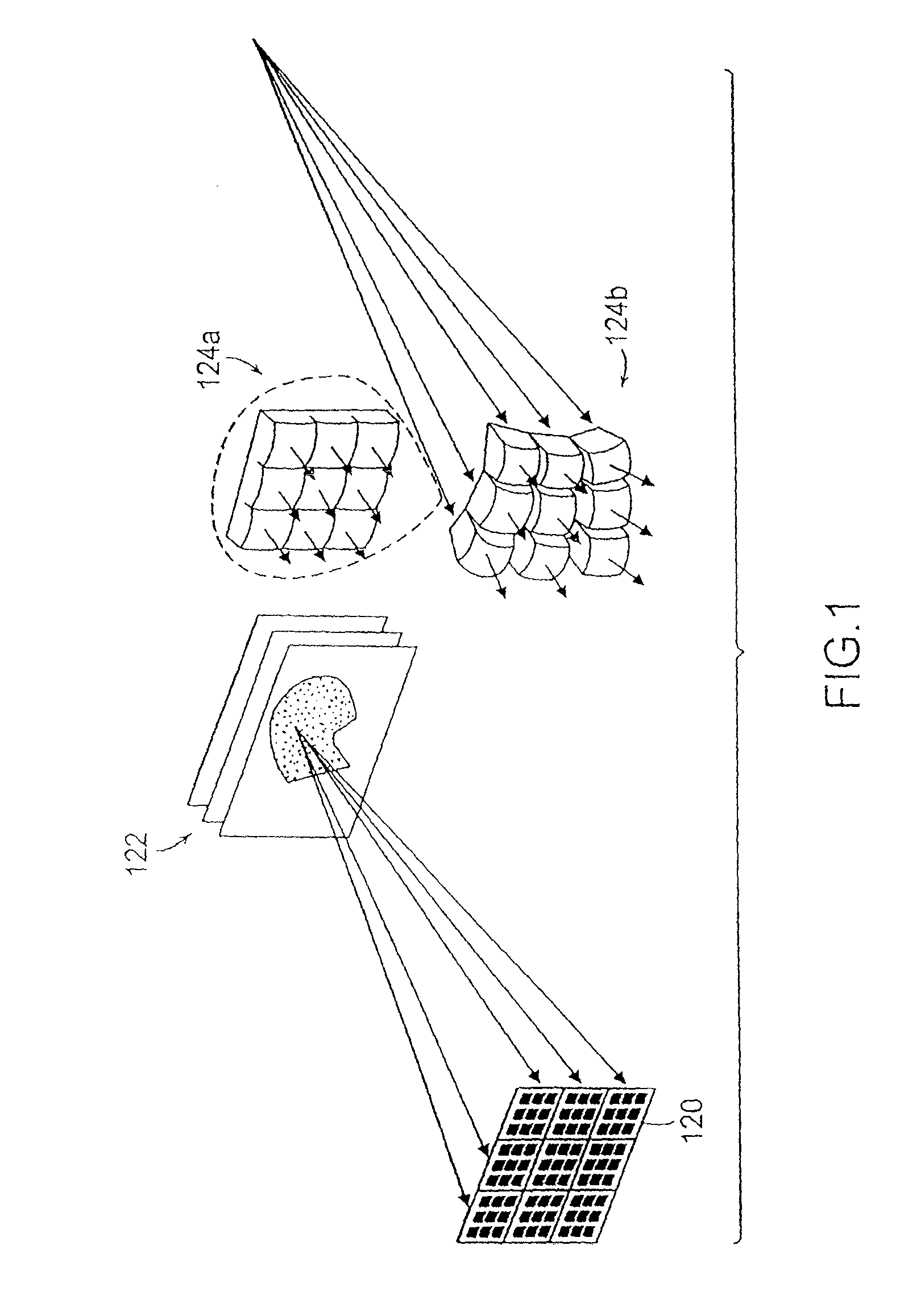
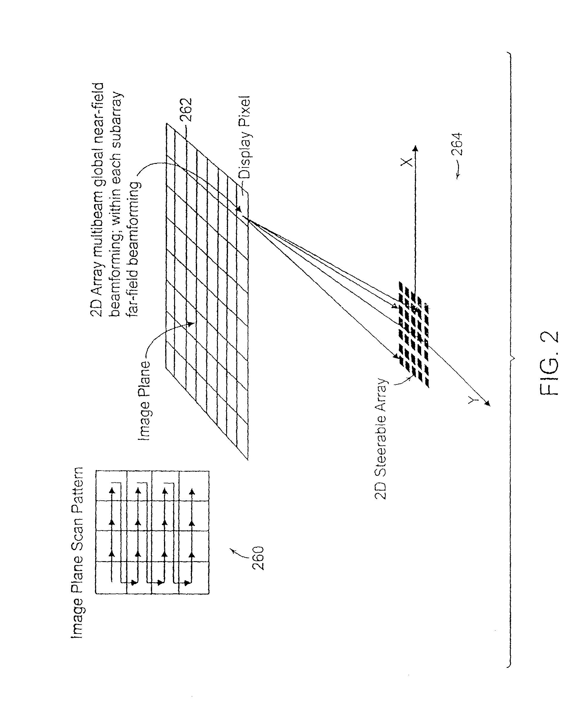
[0058]The objective of the beamforming system is to focus signals received from an image point onto a transducer array. By inserting proper delays in a beamformer to wavefronts that are propagating in a particular direction, signals arriving from the direction of interest are added coherently, while those from other directions do not add coherently or cancel. For real-time three-dimensional applications, separate electronic circuitry is necessary for each transducer element. Using conventional implementations, the resulting electronics rapidly become both bulky and costly as the number of elements increases. Traditionally, the cost, size, complexity and power requirements of a high-resolution beamformer have been avoided by “work-around” system approaches. For real-time three-dimensional high-resolution ultrasound imaging applications, an electronically steerable two-dimensional beamforming processor based on a delay-and-sum computing algorithm is chosen.

[0059]The concept of an elec...


PUM


Abstract

The present invention relates to an ultrasound imaging system in which the scan head either includes a beamformer circuit that performs far field subarray beamforming or includes a sparse array selecting circuit that actuates selected elements. When used with second stage beamforming system, three dimensional ultrasound images can be generated.

Description

CROSS REFERENCE TO RELATED APPLICATION[0001]This application is a continuation-in-part of International Application No. PCT / US09 / 56995 filed on Sep. 15, 2009, which is a continuation-in-part of U.S. application Ser. No. 12 / 286,555 filed on Sep. 30, 2008 and claims priority to U.S. Application No. 61 / 192,063 filed on Sep. 15, 2008 by Chiang et al., entitled: “Ultrasound 3D Imaging System.” This application also claims priority to U.S. application Ser. No. 11 / 474,098 filed Jun. 23, 2006 and of International Application No. PCT / US2007 / 014526 filed Jun. 22, 2007. The entire contents of the above applications are incorporated herein by reference.BACKGROUND OF THE INVENTION[0002]Medical ultrasound imaging has become an industry standard for many medical imaging applications. Techniques have been developed to provide three dimensional (3D) images of internal organs and processes using a two dimensional (2D) transducer array. These systems require thousands of beamforming channels. The powe...

Claims


Application Information

Patent Timeline
Patent Type & Authority Applications(United States)
IPC IPC(8): A61B8/14
CPCA61B8/08G10K11/346A61B8/14A61B8/4411A61B8/4472A61B8/4483A61B8/483A61B8/543G01S7/52079G01S7/5208G01S7/52082G01S7/52085G01S7/52095G01S15/8925G01S15/8927G01S15/8959G01S15/8961G01S15/8993A61B8/0883A61B8/4488A61B8/145A61B8/4444A61B8/466A61B8/488A61B8/52A61B8/54A61B8/565G01S15/8913
Inventor CHIANG, ALICE M.WONG, WILLIAMBROADSTONE, STEVEN R.
Owner TERATECH CORP
Why Eureka
Try Eureka