Method and apparatus for quasi-fractional intense pulse light resurfacing

a pulse light and quasi-fractional technology, applied in the field of methods and apparatus for quasi-fractional intense pulse light resurfacing, can solve the problems of extremely complex research on suitable materials, and achieve the effects of avoiding the delivery of too much energy, uniform temperature increase, and high temperatur

Inactive Publication Date: 2010-07-08
MATTIOLI ENG
View PDF10 Cites 4 Cited by
  • Summary
  • Abstract
  • Description
  • Claims
  • Application Information

AI Technical Summary

Benefits of technology

[0020]A non-transparent shield with a matrix of holes can be provided adjacent a light source to provide the matrix of small spaced spots of light to be incident on an area of skin to be treated. One advantage using a non-transparent shield is to provide a uniform increase of the temperature on the treated area and a higher increase of the temperature where the holes are located. Instead, in the non-transparent shield solution, the increase in the temperature occurs only in the holes. This avoids the delivery of too high energy in the holes for heating the skin and thus limiting the possible damages to the skin that occurs when the energy per square centimeter is too high, i.e. more than 30 Joule / square centimeters. One material that has been found suitable for use in a shield for this application is Aluminum Oxide, with holes laser drilled in the shield. The research of the suitable material has been extremely complex. There is the need to avoid increase of the temperature of the shield during the application, but at the same time provide a sufficient amount (e.g., 75%) of attenuation. The Aluminum Oxide shield reflects 70% of the radiation and transmit the radiation with small attenuation around 5%, thus avoiding increase of the temperature of the shield.

Problems solved by technology

The research of the suitable material has been extremely complex.

Method used


Image

  • Method and apparatus for quasi-fractional intense pulse light resurfacing
  • Method and apparatus for quasi-fractional intense pulse light resurfacing
  • Method and apparatus for quasi-fractional intense pulse light resurfacing

Examples


first embodiment

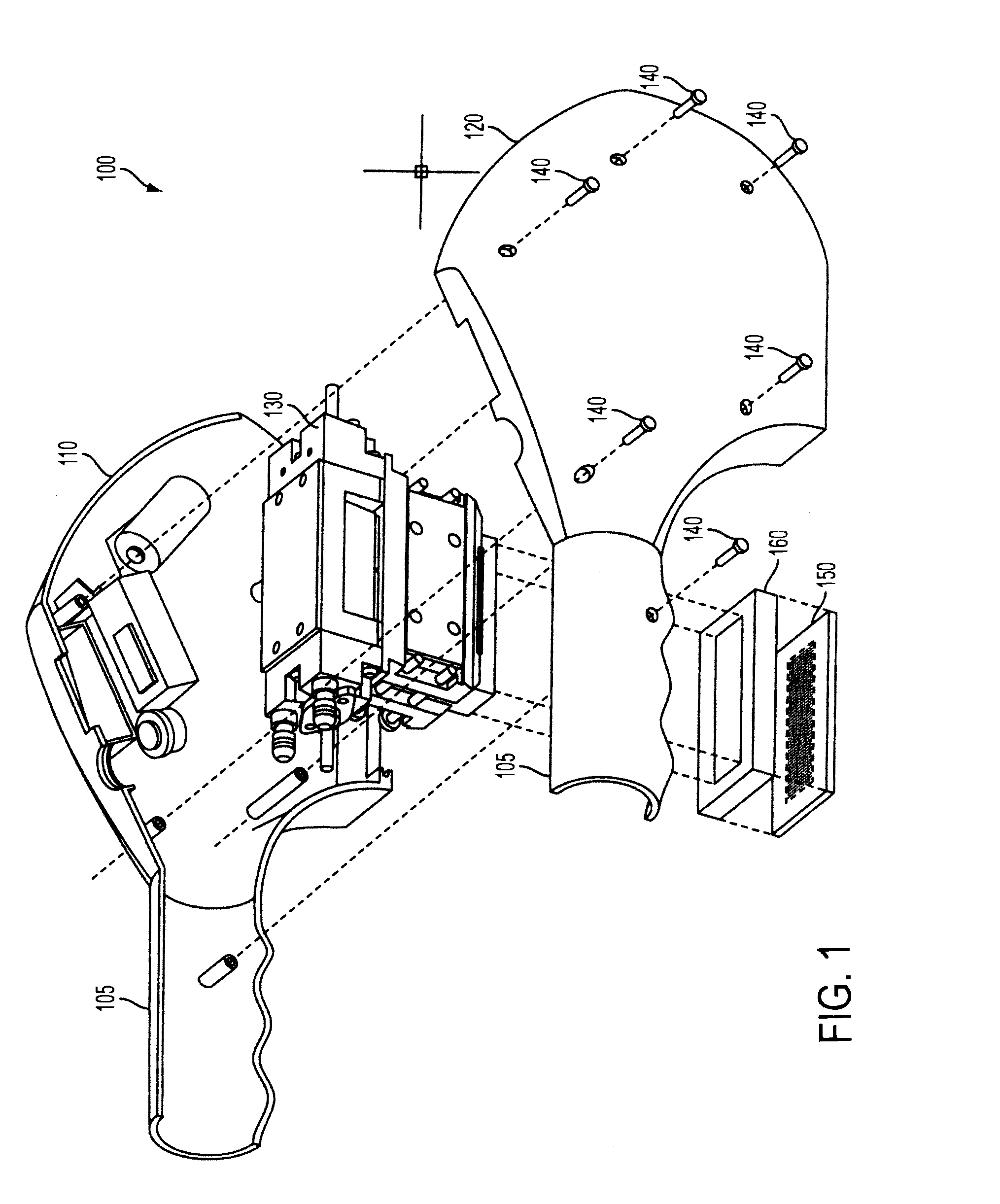
[0034]In the first embodiment, the shield 150 is made of a ceramic material, so that the non-hole portions of the shield 150 allow light from the light source 130 to pass through those portions of the shield 150 in an attenuated manner. In one possible implementation, light from the light source 130 passes through the non-hole portions of the shield 150 at 75% of their output light power, thereby resulting in a 25% attenuation due to the ceramic material making up the shield 150 being in the light path to the patient's skin. Other attenuation amounts, such as 15% to 35%, may be utilized while remaining within the spirit and scope of the invention.

[0035]By controlling the light amount to be incident on the patient's skin by way of the holes of the shield 150 and by controlling the total amount of light to be incident on the patient's skin by using a shield 150 made of a ceramic material, all portions of the patient's skin are subject to at least some amount of light (and thus are tre...

second embodiment

[0037]In a second embodiment, the light source 130 is a CO2 laser operated in a fractional mode, i.e., with a matrix of dots, as described in Italian Patent No. 01286634 (F196A118). The CO2 laser is used to output a single large diameter light beam (non-fractional mode), whereby the combination of the CO2 laser and the shield provides for a single light beam with a large diameter, which is similar to the output light pattern obtained by using a small diameter laser beam and a wobbling mirror as described in Italian Patent No. 01286634 (F1196A118).

[0038]In the first and second embodiments, the use of fractional light generates localized “injuries” on the skin, in order that the spots of injured skin are surrounded by healthy tissue (whereby the healthy tissue is heated a little in order to stimulate regrowth). This is accomplished by creating hot spots where the temperature is well over the damaging temperature value of the epidermis cell, whereby the hot spots are surrounded by area...


PUM


Abstract

A system and method for treating a skin target area includes one or more RF electrodes adapted to provide RF energy for heating the skin target area. A quasi-fractional light unit is adapted to provide optical spots of energy having a wavelength not greater than 1200 nm for heating the skin target area. The RF electrodes and the quasi-fractional light unit are configured to provide energy essentially simultaneously to the skin target area to heat the entire target in non-uniform manner by way of a matrix of spots each having a predetermined diameter.

Description

RELATED APPLICATIONS[0001]This application is a Continuation-In-Part of U.S. patent application Ser. No. 12 / 350,466, filed on Jan. 8, 2009, the disclosure of which is incorporated in its entirety into this application herein by reference.BACKGROUND OF THE INVENTION[0002]1. Field of the Invention[0003]The present invention relates to a method and apparatus for applying to the skin, in a controlled manner, light to the skin in order to heat and selectively damage thin superficial layers of the skin, thereby inducing a renewal process of the epidermis.[0004]2. Description of the Related Art[0005]It is well known in the skin treatment art that in order to renew the epidermis layer, induced damage of the skin is required. One such method uses laser radiation that is incident on the skin and that generates several effects on the skin, depending on the wavelength of the laser radiation, the pulse duration of the laser energy applied to the skin, and the radiation energy provided to the ski...

Claims


Application Information

Patent Timeline
Patent Type & Authority Applications(United States)
IPC IPC(8): A61B18/20A61B18/18
CPCA61B18/14A61B18/203A61B2018/00994A61B2018/00458A61B2018/204A61B2018/00452
Inventor BERNABEI, GIAN FRANCO
Owner MATTIOLI ENG
Why Eureka
Try Eureka