Intravascular stent for treating vulnerable plaque and method of use

a stent and plaque technology, applied in the field of intravascular stents, can solve the problems of unsatisfactory non-uniform force distribution and arteries may develop vulnerable plaque, and achieve the effects of good vessel wall coverage, and increased vessel wall coverag

Inactive Publication Date: 2010-07-08
ABBOTT CARDIOVASCULAR
View PDF9 Cites 4 Cited by
  • Summary
  • Abstract
  • Description
  • Claims
  • Application Information

AI Technical Summary

Benefits of technology

[0007]In one embodiment of the invention, the stent has a distal and proximal section formed of rings or cylindrical elements and links. The rings and links are configured so that the metallic surface area (metal-to-artery ratio) is less than 20% and preferably is between about 20% and 10%, thus providing good scaffolding and providing a more cylindrical lumen. The stent includes a first side of the circumference and a second side of the circumference with the second side being weaker than the first side. The weakness in the second side may be induced by making the struts and links on the second side smaller than the struts and links on the first side, which causes the second side to scaffold less. In use, the second side of the stent is aligned with an area of vulnerable plaque. Being weaker, the second side of the stent restrains the balloon less during stent expansion than does the first side of the stent. Therefore, the second side of the stent expands at a quicker rate than the first side and transfers more stress to the body lumen to induce extra force at the vulnerable plaque when the stent is implanted in an attempt to rupture the fibrous cap over the vulnerable plaque. Conversely, the first side of the stent protects healthy vessel tissue from expansion forces of the stent.
[0008]The cylindrical rings and links can have various configurations. In one embodiment, each of the cylindrical rings making up the stent have a proximal end and a distal end and a cylindrical plane defined by a cylindrical outer wall surface that extends circumferentially between the proximal end and the distal end of the cylindrical ring. The cylindrical rings are interconnected by at least one link which attaches one cylindrical ring to an adjacent cylindrical ring. The links are positioned substantially within the cylindrical plane of the outer wall surface of the cylindrical rings. The design of the links and their placement nested within a W-shaped member provides for uniform scaffolding and a high degree of vessel wall coverage throughout the stent.
[0010]While the cylindrical rings and links generally are not separate structures, they have been conveniently referred to as rings and links for ease of identification. Further, the cylindrical rings can be thought of as comprising a series of U-, W- and Y-shaped structures in a repeating pattern. Again, while the cylindrical rings are not divided up or segmented into U's, W's and Y's, the pattern of the cylindrical rings resemble such configuration. The U's, W's and Y's promote flexibility in the stent primarily by flexing and by tipping radially outwardly as the stent is delivered through a tortuous vessel.
[0011]The links are positioned to be within the curved part of the W-shaped portion which generally increases the amount of vessel wall coverage. Since the link does not expand when the stent is expanded, it will continue to provide good vessel wall coverage even as the curved part of the W-shaped portion spreads apart as the stent is expanded.
[0015]The stents of the embodiments described above may also be made of a superelastic material with the memory set in a crimped configuration, thereby making the stent self contracting. In this embodiment, the contraction forces of the stent cause the stent to hold onto the balloon. During use, the balloon is inflated and the stent expanded until the fibrous cap is ruptured, after which the balloon is deflated. During deflation of the balloon, the contraction forces of the stent help reduce the profile of the balloon as the stent and catheter assembly are withdrawn from the patient.

Problems solved by technology

A nonuniform force distribution may not be desirable because the healthy portion of a vessel is typically the thinnest and weakest and consequently stretches more than the diseased portion.
Further, some coronary arteries may develop vulnerable plaque which may require treatment through stenting.

Method used


Image

  • Intravascular stent for treating vulnerable plaque and method of use
  • Intravascular stent for treating vulnerable plaque and method of use
  • Intravascular stent for treating vulnerable plaque and method of use

Examples


Embodiment Construction

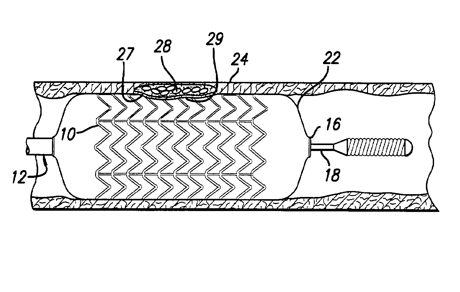
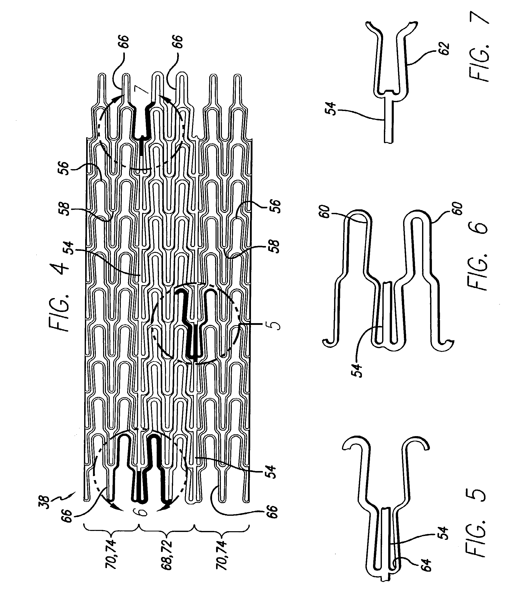
[0036]The present invention stent improves on existing stents by providing concentrated stress points about the circumference of the stent. The design of the stent increases pressure against diseased portions of the artery, such as vulnerable plaque, while inducing less stress against healthier portions of the artery during stent opening. The stent also facilitates rupture of the fibrous cap for controllably releasing the vulnerable plaque contents during stent opening.

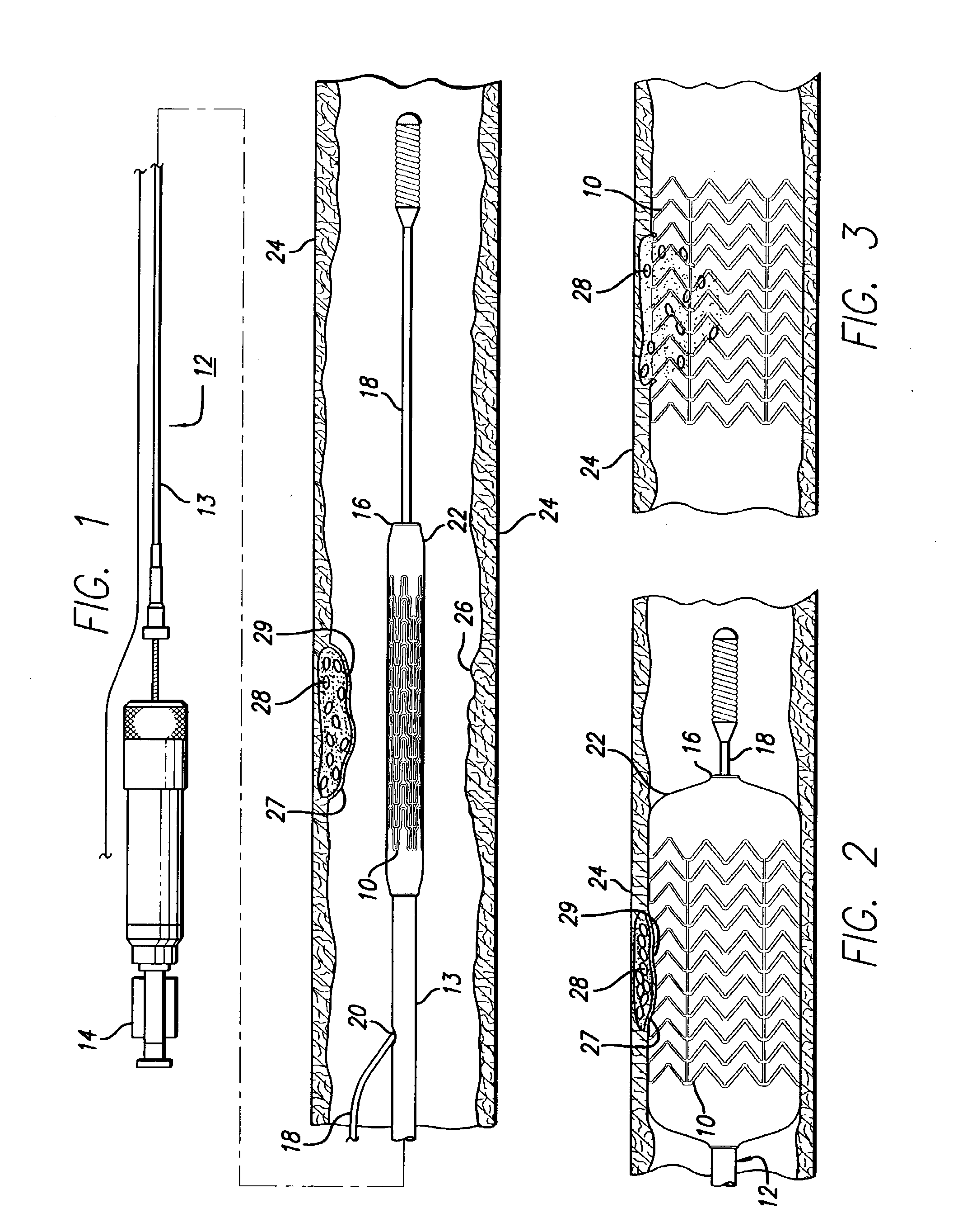
[0037]Turning to the drawings, FIG. 1 depicts stent 10 of the present invention mounted on a catheter assembly 12 which is used to deliver the stent and implant it in a body lumen, such as a coronary artery, peripheral artery, or other vessel or lumen within the body. The catheter assembly includes a catheter shaft 13 which has a proximal end 14 and a distal end 16. The catheter assembly is configured to advance through the patient's vascular system by advancing over a guide wire by any of the well known methods of an...


PUM


Abstract

An expandable stent is implanted in a body lumen, such as a coronary artery, peripheral artery, or other body lumen for rupturing a fibrous cap to controllably release vulnerable plaque. The invention provides for a an intravascular stent having a plurality of cylindrical rings connected by links. The stent includes struts and links of varying strengths about the circumference of the stent. The weaker struts and links require less force to open and, hence, may apply more stress to rupture the fibrous cap while the stronger struts and links protect the healthy portions of the body lumen. In another embodiment, the stent may include stress concentrators positioned on outer surfaces of the links. The stress concentrators are aligned with the fibrous cap prior to stent expansion so that upon stent expansion, the stress concentrators induce stress to rupture the fibrous cap, thereby releasing the vulnerable plaque.

Description

BACKGROUND OF THE INVENTION[0001]This invention relates to vascular repair devices, and in particular intravascular stents, which are adapted to be implanted into a patient's body lumen, such as a blood vessel or coronary artery, to maintain the patency thereof. Stents are particularly useful in the treatment of atherosclerotic stenosis in arteries and blood vessels.[0002]Stents are generally tubular-shaped devices which function to hold open a segment of a blood vessel or other body lumen such as a coronary artery. They also are suitable for use to support and hold back a dissected arterial lining that can occlude the fluid passageway. At present, there are numerous commercial stents being marketed throughout the world.[0003]Balloon dilatation catheters are sometimes used to pre-dilate a diseased vessel prior to installation of a stent. Some balloon dilatation catheters include cutters, or atherotomes, which are placed longitudinally along the length of the balloon. The cutters cre...

Claims


Application Information

Patent Timeline
Patent Type & Authority Applications(United States)
IPC IPC(8): A61B17/22A61F2/82
CPCA61F2/915A61F2002/91566A61F2230/0054A61F2230/0013A61F2250/0036
Inventor COX, DANIEL L.
Owner ABBOTT CARDIOVASCULAR
Why Eureka
Try Eureka