Automotive braking control apparatus and method thereof

Inactive Publication Date: 2010-07-08
TOYOTA JIDOSHA KK
View PDF4 Cites 16 Cited by
  • Summary
  • Abstract
  • Description
  • Claims
  • Application Information

AI Technical Summary

Benefits of technology

[0009]The invention provides an automotive braking control apparatus and a method of controlling an automotive braking control apparatus that controls a regenerative braking system and a friction braking system, wherein a drive system control unit receives a signal indicating a target regenerative braking force from a brake system control unit and controls the regenerative braking system, the automotive braking control apparatus making it possible to regenerate the largest possible energy without causing an unintentional backward movement of a vehicle by preventing a slow response to a control due to communication, which is likely to occur when the regenerative braking system is stopped.
[0015]According to the aspect of the invention described above, the automotive braking control apparatus, which controls the regenerative braking system and the friction braking system based on the amount by which the operating member is operated by a driver to apply a brake, includes the brake system control unit that controls the brake system and the drive system control unit that controls the drive system. The brake system, control unit includes the target braking force calculation unit that sets the target braking force based on the amount by which the operating member is operated by the driver, and the regenerative braking force / friction braking force allocation calculation unit that allocates the target braking force between the target regenerative braking force and the target friction braking force based on the driving conditions of the vehicle, and outputs a signal indicating the allocated target regenerative braking force to the drive system control unit. The drive system control unit includes the regenerative braking control unit that controls the regenerative braking system based on the target regenerative braking force indicated by the signal received from the brake system control unit, the regeneration stop timing determination unit that determines the regeneration stop timing based on the vehicle driving conditions, and the regenerative braking stop unit that stops the regenerative braking system. Therefore, the drive system control unit determines an appropriate regeneration stop timing and stops the regenerative braking system at the appropriate timing. Accordingly, there is provided the automotive braking control apparatus which makes it possible to regenerate the largest possible energy without causing an unintentional backward movement of the vehicle by preventing a slow response to a control due to communication, which is likely to occur when the regenerative braking system is stopped.

Problems solved by technology

1) In the section labeled “a” in FIG. 7, although energy regeneration may be available, a regenerative braking operation is stopped, which hinders enhancement of the fuel efficiency.
Therefore, it is difficult to apply an appropriate hydraulic pressure.
However, if the brake ECU outputs the regeneration stop command to the HV-ECU immediately before the vehicle stops (or, at the same time that the vehicle stops) in order to regenerate as much energy as possible, there is a possibility that output of a regenerative torque (negative torque) will continue even after the vehicle stops, which may cause an unintentional backward movement of the vehicle.

Method used


Image

  • Automotive braking control apparatus and method thereof
  • Automotive braking control apparatus and method thereof
  • Automotive braking control apparatus and method thereof

Examples


Embodiment Construction

[0024]An automotive braking control apparatus according to an embodiment of the invention will be described below in detail with reference to the accompanying drawings. Note that, the invention is not limited to this embodiment. Furthermore, the elements in the following embodiment include elements which can easily be conceived by one skilled in the art, or elements which are substantially the same.

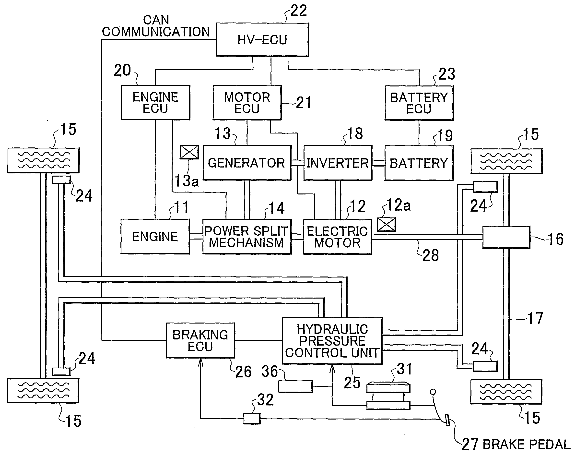
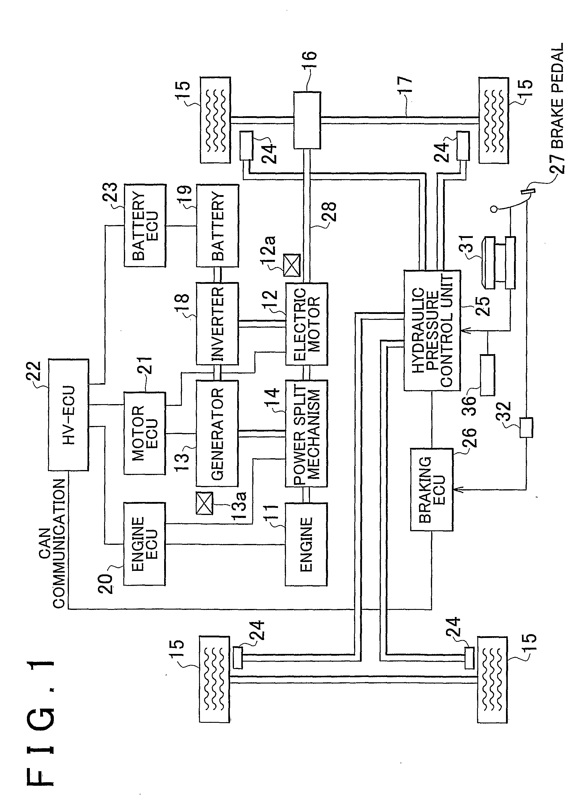
[0025]FIG. 1 is a view schematically showing the structure of a hybrid vehicle including an automotive braking control apparatus according to an embodiment of the invention.

[0026]As shown in FIG. 1, the hybrid vehicle including the automotive braking control apparatus according to the embodiment of the invention is provided with an engine 11 and an electric motor 12 as drive power sources. Further, the hybrid vehicle is provided with a generator 13 that generates electric power using the drive power supplied from the engine 11. The engine 11, the electric motor 12, and the generator 13 ar...


PUM


Abstract

An HV-ECU includes a regenerative braking control unit that controls a regenerative braking system based on the target regenerative braiding force indicated by a signal received from a brake ECU, a regeneration stop timing determination unit that determines a regeneration stop timing, and a regenerative braking stop unit that stops the regenerative braking system when the regeneration stop timing determination unit determines that the regeneration stop timing has been reached.

Description

BACKGROUND OF THE INVENTION[0001]1. Field of the Invention[0002]The invention relates generally to an automotive braking control apparatus and a method of controlling an automotive braking control apparatus, and more specifically to an automotive braking control apparatus and a method of controlling an automotive braking control apparatus that controls a regenerative brake system and a friction brake system based on the amount by which an operating member is operated by a driver.[0003]2. Description of the Related Art[0004]In recent years, there has been proposed a hybrid vehicle including an engine that outputs torque by burning a fuel therein and an electric motor that outputs torque using electric power supplied thereto. The hybrid vehicle travels using the torque transferred from the engine and / or the electric motor to wheels. In such hybrid vehicle, whether the electric motor is driven or stopped is controlled depending on the driving conditions. Thus, whether to use only the t...

Claims


Application Information

Patent Timeline
IPC IPC(8): B60W20/00B60W10/06B60W10/08B60W10/18B60W30/18B60T1/10B60L7/24B60T8/17B60W10/24
CPCB60W10/184B60W30/18127B60T8/4081B60T1/10B60T2270/604B60W2540/12B60W20/00Y02T10/6239B60K6/445B60W10/08Y02T10/62B60W10/18B60W10/24B60W20/13
Inventor IRIE, YOSHIAKI
Owner TOYOTA JIDOSHA KK
Why Eureka
Try Eureka