Heat storage device

a technology of storage device and heat storage device, which is applied in the direction of indirect heat exchanger, domestic cooling apparatus, lighting and heating apparatus, etc., can solve the problems of increased fuel consumption of vehicles, excessive compression of compressors, and large loss of energy, so as to enhance the thermal efficiency of the refrigeration cycle, enhance the thermal efficiency, and reliably liquefy the refrigerant

a technology of storage device and heat storage device, which is applied in the direction of indirect heat exchanger, domestic cooling apparatus, lighting and heating apparatus, etc., can solve the problems of increased fuel consumption of vehicles, excessive compression of compressors, and large loss of energy, so as to enhance the thermal efficiency of the refrigeration cycle, enhance the thermal efficiency, and reliably liquefy the refrigerant

US20100175413A1Inactive Publication Date: 2010-07-15TOYOTA JIDOSHA KK

Image

  • Heat storage device
  • Heat storage device
  • Heat storage device

Examples


Embodiment Construction

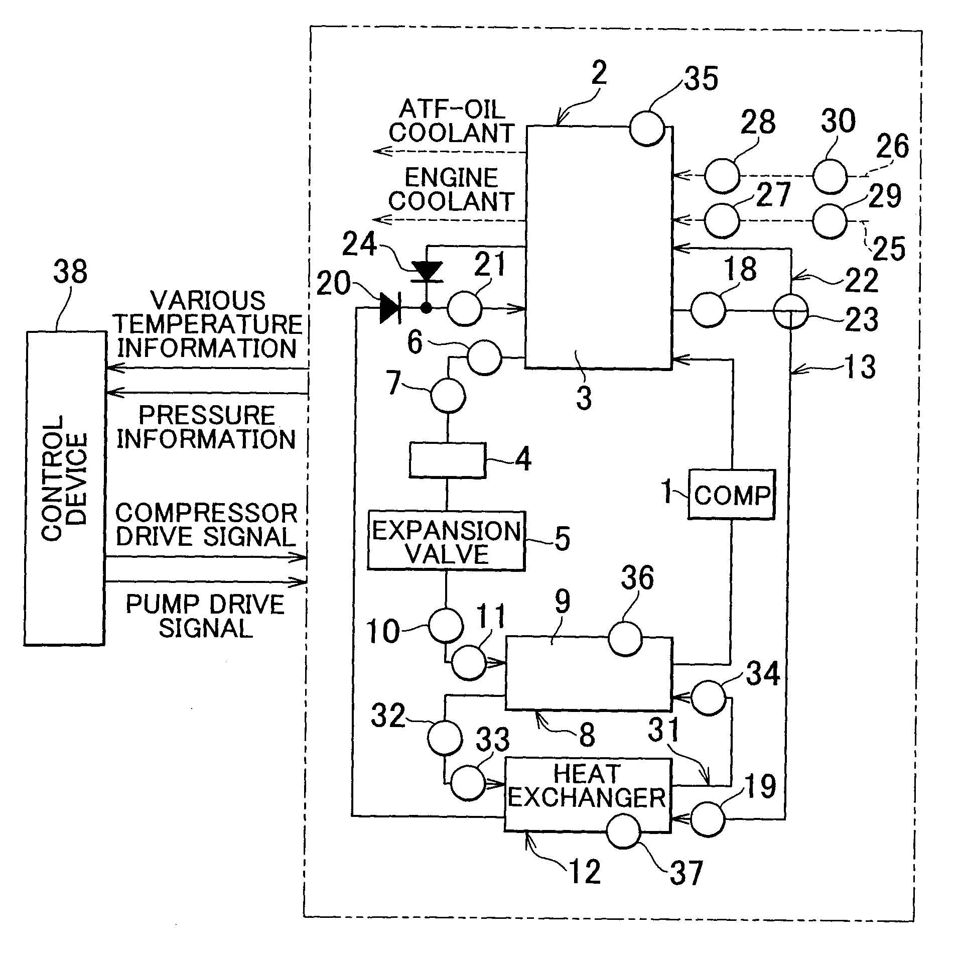
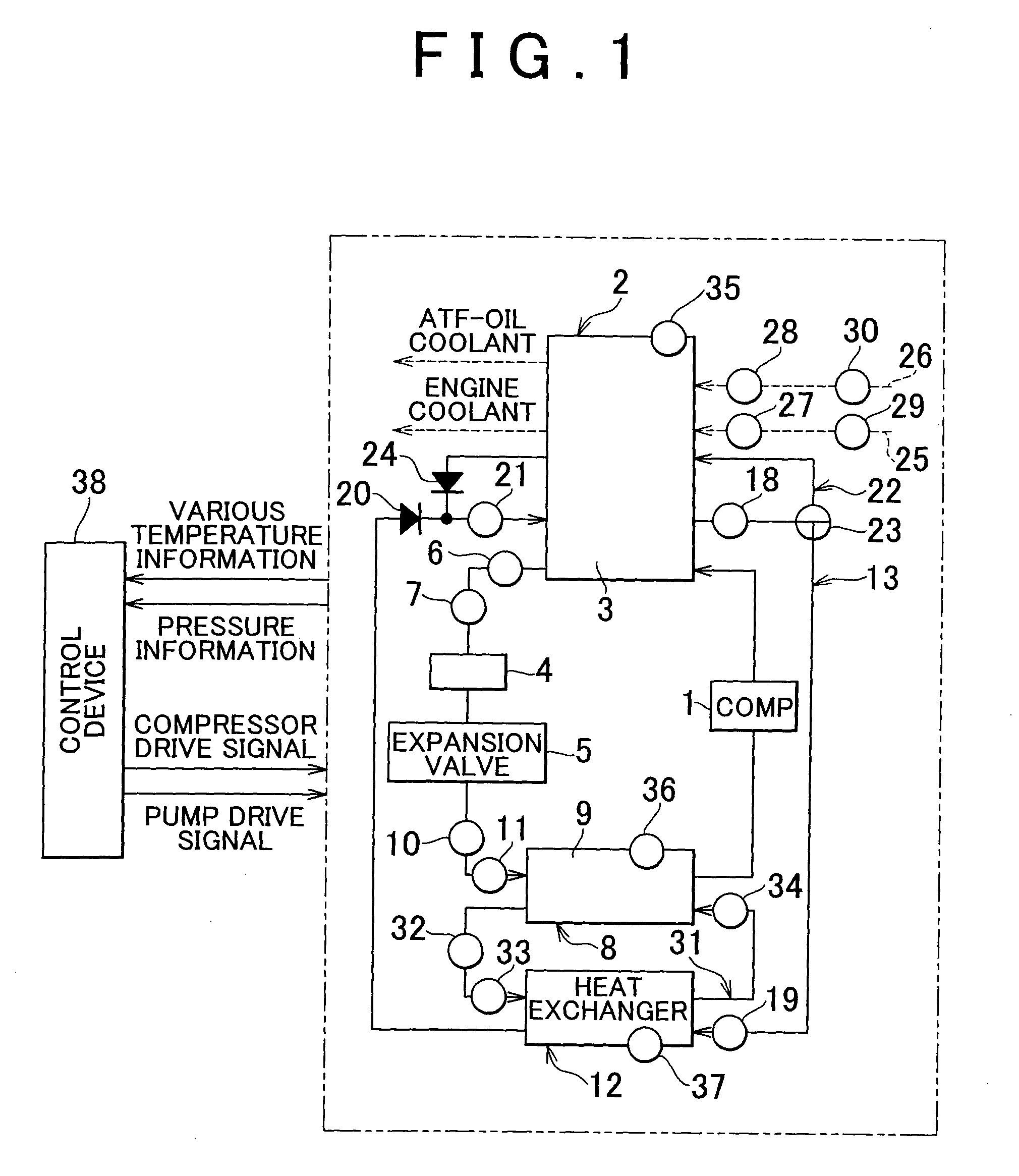
[0037]Next, this invention will be explained in concrete terms. The example shown in FIG. 1 is an example in which this invention has been applied to a condenser and an evaporator for a heat pump that operates on a refrigeration cycle, and, first to explain this refrigeration cycle: a compressor 1, which is driven by a power source such as an engine or an electric motor (neither of these is shown in the figures) or the like, compresses refrigerant, and is connected a heat storage device, such as the condensation device 2 (a condenser), on its discharge side. This heat storage type condensation device 2 liquefies the refrigerant by extracting, with a heat storage material 3, the heat from the refrigerant after its temperature has been elevated by pressurization and compression. The heat storage material 3 corresponds to the “first heat storage material” of the Claims. A sensible heat storage material or a latent heat storage material may be employed as the heat storage material 3, bu...


PUM


Abstract

A heat storage device that includes a first heat storage material and a second heat storage material, both of which accumulate heat by heat exchange with a heat afferent medium, and a changeover device that selectively either performs or intercepts heat storage by the second heat storage material. Accordingly, if the absorption of heat by the first heat storage material has decreased, the changeover device changes flow of the second heat storage material so that heat may be extracted from the heat afferent medium by the second heat storage medium. Thus, when the heat afferent medium is a refrigerant, it is possible to supercool the refrigerant thereof. Furthermore, since heat is extracted from the heat afferent medium and is accumulated, accordingly it is possible to anticipate effective utilization thereof.

Description

BACKGROUND OF THE INVENTION[0001]1. Field of the Invention[0002]The present invention relates to a heat storage device that temporarily accumulates heat (or cold energy) held in a medium such as a refrigerant or the like.[0003]2. Description of the Related Art[0004]In the art related to the invention, a compression type heat pump is known as one example of a heating device. The fundamental construction thereof is that a compressor compresses a refrigerant gas, the refrigerant gas dissipates heat so that it condenses, and then, the refrigerant is expanded adiabatically, and absorbs external heat so that it vaporizes, and thereafter is compressed again. Accordingly, if for example a vehicle is to be air conditioned, the air within the passenger compartment is cooled by taking advantage of the action of the refrigerant to absorb heat, so that the air in the passenger compartment is cooled.[0005]In a vehicle, the power source for propelling the vehicle, such as an engine or the like, is...

Claims


Application Information

Patent Timeline
15 Jul 2010
Publication
US20100175413A1
IPC
F25B13/00
CPC
B60H1/00492; B60H1/00764; B60H2001/00949; B60H2001/00928; B60H1/00885; B60H1/32284
Inventors
TSUBONE, KENJI