Control apparatus for internal-combustion engine with variable valve mechanism

a control apparatus and internal combustion technology, applied in combustion engines, valve arrangements, machines/engines, etc., can solve the problems of increased actual in-cylinder compression ratio and more likely knocking, and achieve the effect of properly suppressing the torque change due to deterioration of combustion during the control mode selection

Inactive Publication Date: 2010-07-15
TOYOTA JIDOSHA KK
View PDF3 Cites 11 Cited by
  • Summary
  • Abstract
  • Description
  • Claims
  • Application Information

AI Technical Summary

Benefits of technology

[0028]According to the eighth aspect of the present invention, the angle of the throttle valve can be appropriately set when the throttle valve is used as the torque control means in the second control mode.
[0029]According to the ninth aspect of the present invention, changes in torque,

Problems solved by technology

When the intake valve is closed near the bottom dead center, an actual in-cyl

Method used


Image

  • Control apparatus for internal-combustion engine with variable valve mechanism
  • Control apparatus for internal-combustion engine with variable valve mechanism
  • Control apparatus for internal-combustion engine with variable valve mechanism

Examples


first embodiment

System Configuration

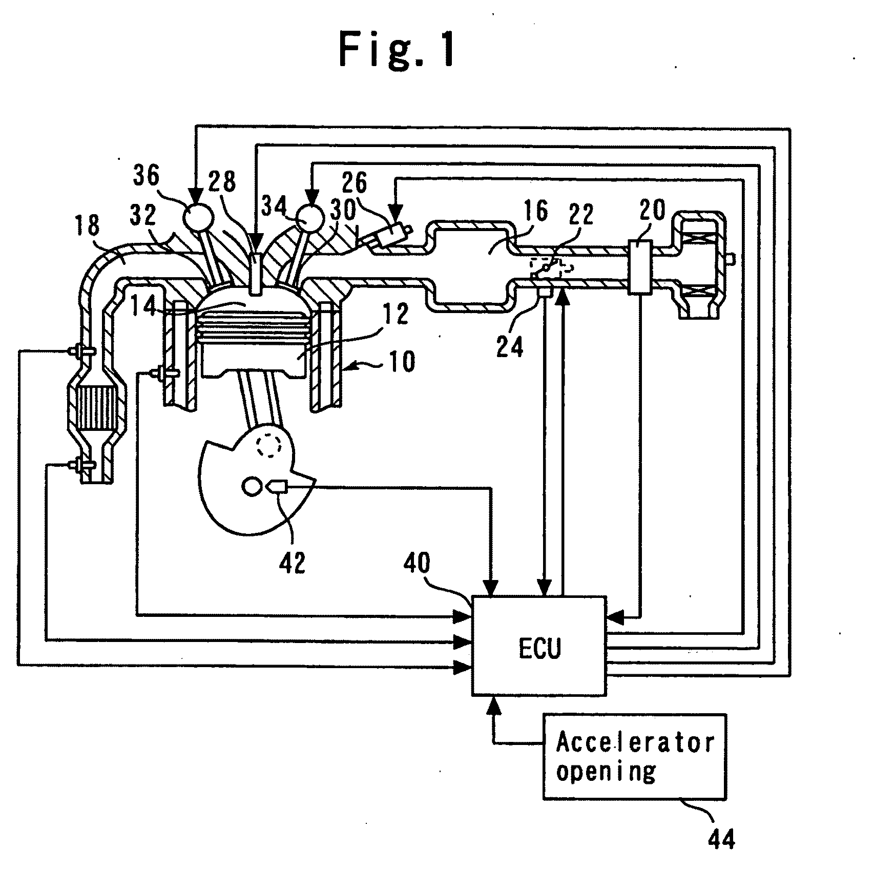
[0045]FIG. 1 is a diagram explaining a configuration of an internal-combustion engine 10 according to a first embodiment of the present invention. The system of the present embodiment includes the internal-combustion engine 10. Also, the present embodiment assumes an inline four-cylinder engine as the internal-combustion engine 10. Each of cylinders of the internal-combustion engine 10 contains a piston 12. Each of the cylinders of the internal-combustion engine 10 has a combustion chamber 14 formed atop the piston 12. An air intake passageway 16 and an exhaust passageway 18 are communicated with the combustion chamber 14.

[0046]An air flow meter 20 is installed near the inlet of the air intake passageway 16 to output a signal representing the flow rate of the air taken into the air intake passageway 16. A throttle valve 22 is installed downstream of the air flow meter 20. The throttle valve 22 is an electronically controlled throttle valve that can control an ope...

second embodiment

[0086]A second embodiment of the present invention will now be described with reference to FIGS. 10 to 12.

[0087]The system according to the second embodiment is implemented by adopting the hardware configuration shown in FIG. 1 and allowing the ECU 40 to execute a routine shown in FIG. 12 instead of the routine shown in FIG. 9.

Feature Portions of the Second Embodiment

[0088]FIG. 10 is a diagram explaining the opening / closing timing of the intake valve 30 used as the second control mode in a second embodiment of the present invention. FIG. 10 shows an example in which, in addition to being opened at a position relatively advanced in angle with respect to the top dead center TDC of air intake, the intake valve 30 has its IVC timing fully retarded to such an extent that blowback of the intake air into the intake passage intentionally occurs to lower an actual compression ratio.

[0089]The IVC timing here of such an extent that the blowback of the intake air intentionally occurs refers to ...

third embodiment

[0109]A third embodiment of the present invention will now be described with reference to FIG. 13.

[0110]The system according to the third embodiment is implemented by adopting the hardware configuration shown in FIG. 1 and allowing the ECU 40 to execute a routine shown in FIG. 13 instead of the routine shown in FIG. 12.

Feature Portions of the Third Embodiment

[0111]The system of the present embodiment is characterized in a technique relating to the torque adjustments performed when the control mode is instantly changed between the IVC variable control and the intake valve closing retardation control (the torque adjustments are detailed in step 300 and the like). More specifically, the present embodiment adjusts a change range of throttle angle TA on the basis of the IVC timing and operating angle of the intake valve 30 existing after the control mode change.

[0112]When the intake valve closing retardation control that uses such opening / closing timing of the intake valve 30 as shown in...


PUM


Abstract

An intake variable valve mechanism 34 is provided that allows closing timing of an air intake valve 30 to be varied. The intake variable valve mechanism 34 has a first control mode that controls IVC timing of the intake valve 30 at an angle-advancing side relative to a certain range including an air intake bottom dead center BDC, and a second control mode that controls the IVC timing of the intake valve 30 at an angle-retarding side relative to the certain range. IVC variable control (first control mode) for making the IVC timing of the intake valve 30 variable according to load is selected for operation in a region of relative low loads, and intake valve closing retardation control (second control mode) for controlling the intake valve 30 in fully retarded IVC timing is selected for operation in a region of relatively high loads.

Description

TECHNICAL FIELD[0001]The present invention relates to a control apparatus for an internal-combustion engine having a variable valve mechanism.BACKGROUND ART[0002]Patent Document 1, for example, discloses a control apparatus for an internal-combustion engine having a variable valve mechanism to make variable the opening and closing timing of an air intake valve and the lift amount thereof. The conventional control apparatus as described in Patent Document 1 is constructed so that when knock is detected, the apparatus executes control to suppress knock and suppress changes in torque. More specifically, as an example of the control performed when knock is detected, the conventional control apparatus operates to increase the opening area of the intake valve as well as to advance the closing timing thereof.[0003]Including the above-mentioned document, the applicant is aware of the following document as a related art of the present invention.[0004][Patent Document 1] Japanese Patent Laid-...

Claims


Application Information

Patent Timeline
IPC IPC(8): F01L1/34
CPCY02T10/18F02D13/0234Y02T10/12
Inventor SHINAGAWA, TOMOHIROTSUJI, KIMITOSHI
Owner TOYOTA JIDOSHA KK
Why Eureka
Try Eureka