Power transmission control device, power transmission device, electronic apparatus, and load state detection circuit

a technology of power transmission control and load state detection, which is applied in the direction of inductance, wireless communication, transportation and packaging, etc., to achieve the effect of easy detection and easy detection of load sta

Active Publication Date: 2010-07-15
SAMSUNG ELECTRONICS CO LTD
View PDF12 Cites 69 Cited by
  • Summary
  • Abstract
  • Description
  • Claims
  • Application Information

AI Technical Summary

Benefits of technology

[0007]An advantage of the invention is to provide a power transmission control device, a power transmission device, an electronic apparatus, and a load state detection circuit that can easily detect the load state.
[0008]A first aspect of the invention provides a power transmission control device provided in a power transmission device included in a contactless power transmission system in which power is transmitted from the power transmission device to a power receiving device by electromagnetically coupling an elementary coil and a secondary coil and the power is supplied to a load of the power receiving device. The power transmission control device includes a load state detection circuit that detects a load state of the power receiving device on the basis of a first signal from a first end of a resonance capacitor forming a resonant circuit with the elementary coil and a second signal from a second end of the resonance capacitor.
[0009]In the first aspect of the invention, the elementary coil and resonance capacitor forms a resonant circuit. The load state detection circuit detects the load state of the power receiving device. Specifically, the load state detection circuit detects the load state of the power receiving device on the basis of the differential signal between the first signal from the first end of the resonance capacitor and the second signal from the s

Problems solved by technology

Unfortunately, in this related-art example, only a signal from one terminal of the primary coil is monitored when detecting the phase.
This causes a problem that when there occurs an environmental variation, such as a voltage vari

Method used


Image

  • Power transmission control device, power transmission device, electronic apparatus, and load state detection circuit
  • Power transmission control device, power transmission device, electronic apparatus, and load state detection circuit
  • Power transmission control device, power transmission device, electronic apparatus, and load state detection circuit

Examples


Embodiment Construction

[0060]Now, an exemplary embodiment of the invention will be described in detail. The embodiment to be described below does not unduly limit the invention as set forth in the appended claims. Also, not all the configurations described in the embodiment are essential as means for solving the above-mentioned problem.

[0061]Electronic Apparatus

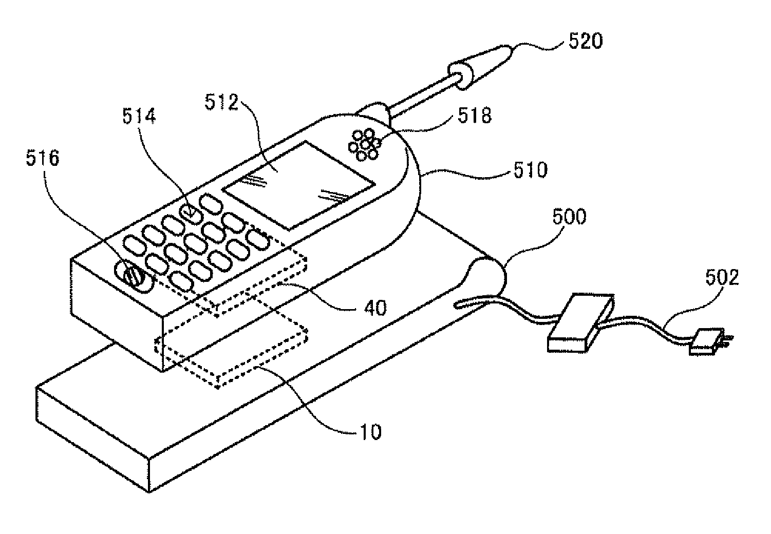
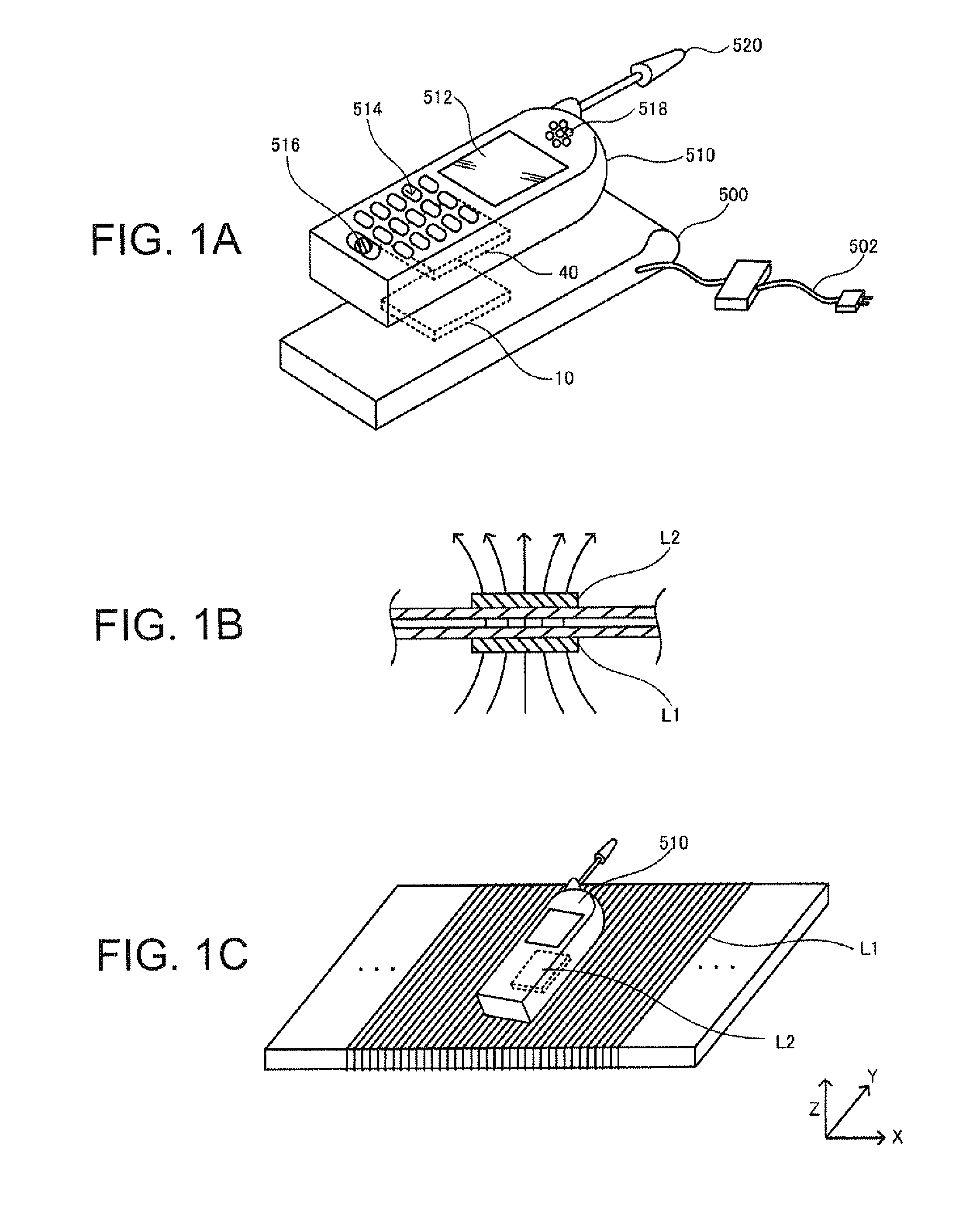
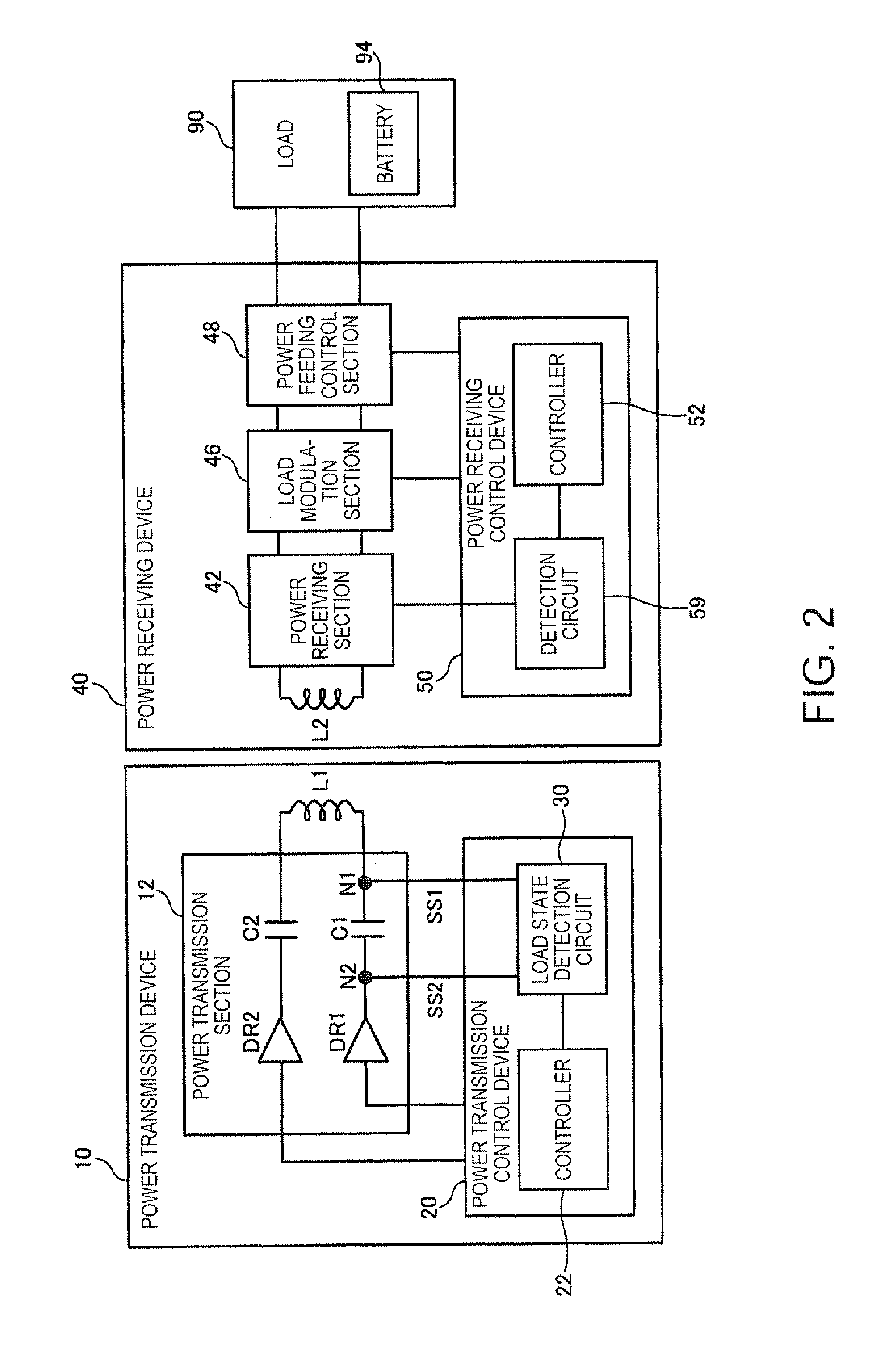
[0062]FIG. 1A shows an example of electronic apparatuses to which a contactless power transmission method according to this embodiment is applicable. An electronic apparatus, charger 500 (cradle), includes a power transmission device 10. An electronic apparatus, cell phone 510, includes a power receiving device 40. The cell phone 510 includes a display 512, such as an LCD, an operation section 514 including buttons, a microphone 516 (voice input section), a speaker 518 (voice output section), and an antenna 520.

[0063]The charger 500 receives power via an AC adapter 502 and transmits the power from the power transmission device 10 to the power recei...


PUM


Abstract

There is provided a power transmission control device provided in a power transmission device included in a contactless power transmission system in which power is transmitted from the power transmission device to a power receiving device by electromagnetically coupling an elementary coil and a secondary coil and the power is supplied to a load of the power receiving device. The power transmission control device includes a load state detection circuit that detects a load state of the power receiving device on the basis of a first signal from a first end of a resonance capacitor forming a resonant circuit with the elementary coil and a second signal from a second end of the resonance capacitor.

Description

[0001]The present application claims a priority based on Japanese Patent Application No. 2009-005556 filed on Jan. 14, 2009, the contents of which are incorporated herein by reference.BACKGROUND[0002]1. Technical Field[0003]The present invention relates to a power transmission control device, a power transmission device, an electronic apparatus, and a load state detection circuit.[0004]2. Related Art[0005]In recent years, the spotlight has been on contactless power transmission (non-contact power transmission) that can transmit power using electromagnetic induction without using a metallic contact. The applications of such contactless power transmission technology include charging of cell phones and household appliances (e.g., handsets). Related-art examples of contactless power transmission technology include JP-A-2006-230032.[0006]Unfortunately, in this related-art example, only a signal from one terminal of the primary coil is monitored when detecting the phase. This causes a pro...

Claims


Application Information

Patent Timeline
IPC IPC(8): H02J17/00H02J7/00H02M3/28
CPCH02J5/005H02J7/025H04B5/0081H04B5/0037H04B5/0031H02J50/90H02J7/00034H02J50/12H02J50/60H02J50/80
Inventor AOYAMA, TAKASHITOKUNAGA, MASAKAZU
Owner SAMSUNG ELECTRONICS CO LTD
Why Eureka
Try Eureka