Discharge lamp operating device, illumination device and liquid crystal display device

a technology of liquid crystal display device and discharge lamp, which is applied in the direction of instruments, light sources, electrical devices, etc., can solve the problems of high voltage, non-uniformity of luminosity, and high voltage between the output section and the socket section, and achieve the effect of detecting the disconnection of filaments

Inactive Publication Date: 2010-07-15
PANASONIC CORP
View PDF8 Cites 9 Cited by
  • Summary
  • Abstract
  • Description
  • Claims
  • Application Information

AI Technical Summary

Benefits of technology

[0012]The object of the present invention is to provide a discharge lamp operating device, an illumination device and a liquid crystal display device, whereby it is possible to detect disconnection of filaments in a stable fashion, without increasing the number of components.

Problems solved by technology

Therefore, it is not possible to ignore the effects of the parasitic capacitance between the high impedance load and the housing, a bias occurs in the luminosity distribution of the discharge lamps due to the effects of current leaking to the housing, and hence there is a problem in that the luminosity becomes non-uniform.
However, in a discharge lamp operating device which operates HCFL at high frequency by means of an inverter circuit, if the filament of a discharge lamp becomes disconnected, for instance, when in a loadless state (a state where the discharge lamp is removed) or at the end of the lifespan of the lamp, or the like, then if the oscillation of the inverter circuit is continued, a high voltage will occur between the output section and the socket section, and there is a risk of danger, such as electric shock.
Accordingly, in the discharge lamp operating device in Patent Document 1, there is a problem in that the accuracy of detecting disconnection of the filaments is low.
In this case, if stresses, such as the starting voltage of the discharge lamps, and the like, are taken into account, then it is necessary to arrange a plurality of resistances in series, and there is a problem in that the number of components becomes greater.
Furthermore, if the direct current power source section and the discharge lamp load need to be isolated, then a separate power source for detecting disconnection of the filaments becomes necessary and there is a problem in that the number of components becomes greater.

Method used


Image

  • Discharge lamp operating device, illumination device and liquid crystal display device
  • Discharge lamp operating device, illumination device and liquid crystal display device
  • Discharge lamp operating device, illumination device and liquid crystal display device

Examples


first embodiment

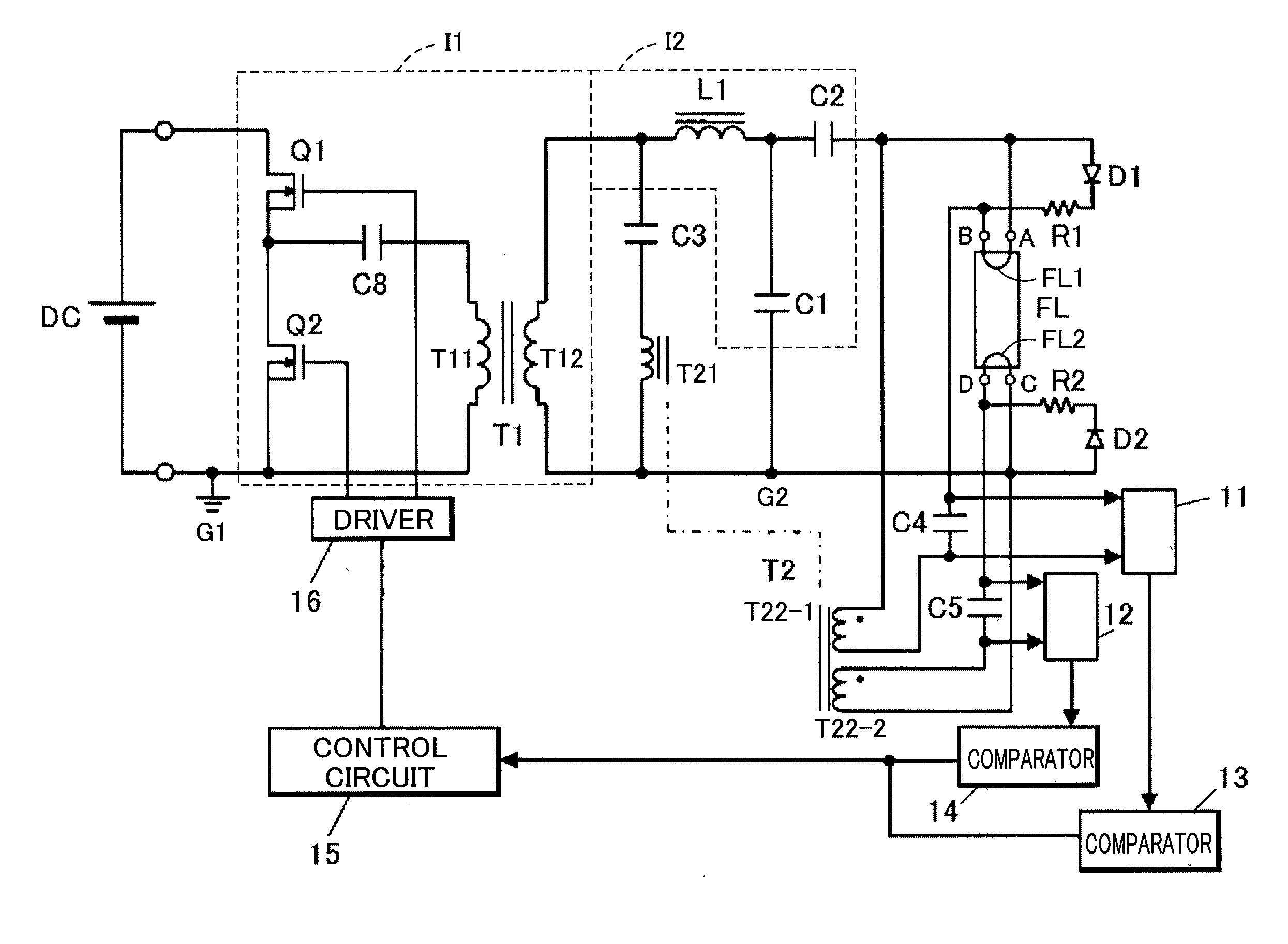
[0025]FIG. 1 is a circuit diagram of a discharge lamp operating device according to a first embodiment of the present invention. A direct current power source unit DC is constituted by a power source circuit which outputs a prescribed DC voltage, and comprises, for example, a rectifying circuit which performs full-wave rectification of a commercial AC voltage, and a boost chopper circuit which boosts and smoothes the full-wave rectified commercial AC voltage.

[0026]The negative electrode of the DC power source unit DC is connected to a primary side reference potential G1 (ground). A half bridge circuit constituted by serially connected switching elements Q1 and Q2 is connected between the positive electrode and the negative electrode of the DC power source unit DC. The switching elements Q1 and Q2 are constituted by power MOSFET, for example, and switch alternately on and off at high frequency by receiving the output of a control circuit 15 via a driver 16. A primary winding T11 of a...

second embodiment

[0049]FIG. 5 shows a circuit diagram of a discharge lamp operating device according to a second embodiment of the present invention. A characteristic feature of the present embodiment is that, in order to detect the DC voltage components of the preheating capacitors C4, C5, the DC voltage component at the terminals B and D is detected with reference to the secondary-side reference potential G2.

[0050]A detection circuit 11b for detecting the DC voltage component with respect to the secondary-side reference potential G2 is connected to the terminal B. Furthermore, a detection circuit 12d for detecting the DC voltage component with respect to the secondary-side reference potential G2 is connected to the terminal D.

[0051]The detection circuit 11b comprises resistances R1b, R2b and a capacitor C1b. The resistance R1b is connected in series to a parallel circuit comprising the resistance R2b and the capacitor C1b. The time constant of the resistances Rib and R2b and the capacitor C1b is s...

third embodiment

[0069]The discharge lamp operating device according to the third embodiment is characterized in employing a composition which, of detection of disconnection of the filament and detection of the end of the lifespan of the discharge lamp FL, is able to detect only disconnection of the filament. FIG. 6 shows a circuit diagram of the detection circuits 11a, 11b in a discharge lamp operating device according to a third embodiment of the present invention. Here, the detection circuit 11a relating to the filament FL1 is depicted, but it is also possible to employ a detection circuit having a similar composition to the detection circuit 11a, in relation to the filament FL2.

[0070]The detection circuit 11a comprises resistances R1a, R2a, R3a, a capacitor C1a and a DC power source unit V1. The resistance R1a is connected to the secondary side reference potential G2 via the capacitor C1a. The capacitor C1a is connected to the negative terminal of a comparator 13′. The resistance R2a is connecte...


PUM


Abstract

A series circuit comprising a diode and a resistance is connected in parallel to a filament, and a series circuit comprising a diode and a resistance is connected in parallel to a filament. The filaments are preheated by a preheating current supplied from secondary windings of a preheating transformer, via preheating capacitors. Detection circuits detect DC voltage components of the preheating capacitors. Comparators compare the DC voltage components of the preheating capacitors with a reference voltage. The comparators cause a control circuit to protect the inverter circuit if an abnormality of the filaments is detected.

Description

TECHNICAL FIELD[0001]The present invention relates to a discharge lamp operating device which operates a discharge lamp having a filament at high frequency, and to an illumination device and liquid crystal display device using same.BACKGROUND ART[0002]In recent years, light sources which illuminate a display surface from the rear side (backlights) have been commonly used in liquid crystal display devices for personal computers, OA devices, liquid crystal televisions, or the like, and illumination devices such as signboard lamps. Of these, a direct backlight is known which comprises a plurality of discharge lamps arranged on a reflector plate and a diffuser plate which is disposed over the discharge lamps.[0003]In the field of liquid crystal display devices, there are demands for large screen size, high luminosity and uniformity. Consequently, there is a tendency for the number of discharge lamps used per device to increase, and for the tube voltage of the discharge lamps used to ope...

Claims


Application Information

Patent Timeline
Patent Type & Authority Applications(United States)
IPC IPC(8): H05B41/26
CPCH05B41/295Y10S315/04H05B41/2985
Inventor NARUO, MASAHIRO
Owner PANASONIC CORP
Why Eureka
Try Eureka