Circuit and method for controlling the point of maximum power for solar energy source and solar generator incorporating said circuit

Inactive Publication Date: 2010-07-15
MPPC TECH
View PDF3 Cites 146 Cited by
  • Summary
  • Abstract
  • Description
  • Claims
  • Application Information

AI Technical Summary

Benefits of technology

[0002]The present invention has its main field of application in the industry destined to the design of

Problems solved by technology

Problems arise when the designer of the power system tries to get the solar panel to work at the PMP for obvious reasons of reduction of mass and cost.
The drawback is that it is not possible without affecting the continuity of the voltage supplied to the user.
This is a drawback, because the unit or power circuit and, therefore, the s

Method used


Image

  • Circuit and method for controlling the point of maximum power for solar energy source and solar generator incorporating said circuit
  • Circuit and method for controlling the point of maximum power for solar energy source and solar generator incorporating said circuit
  • Circuit and method for controlling the point of maximum power for solar energy source and solar generator incorporating said circuit

Examples


Example

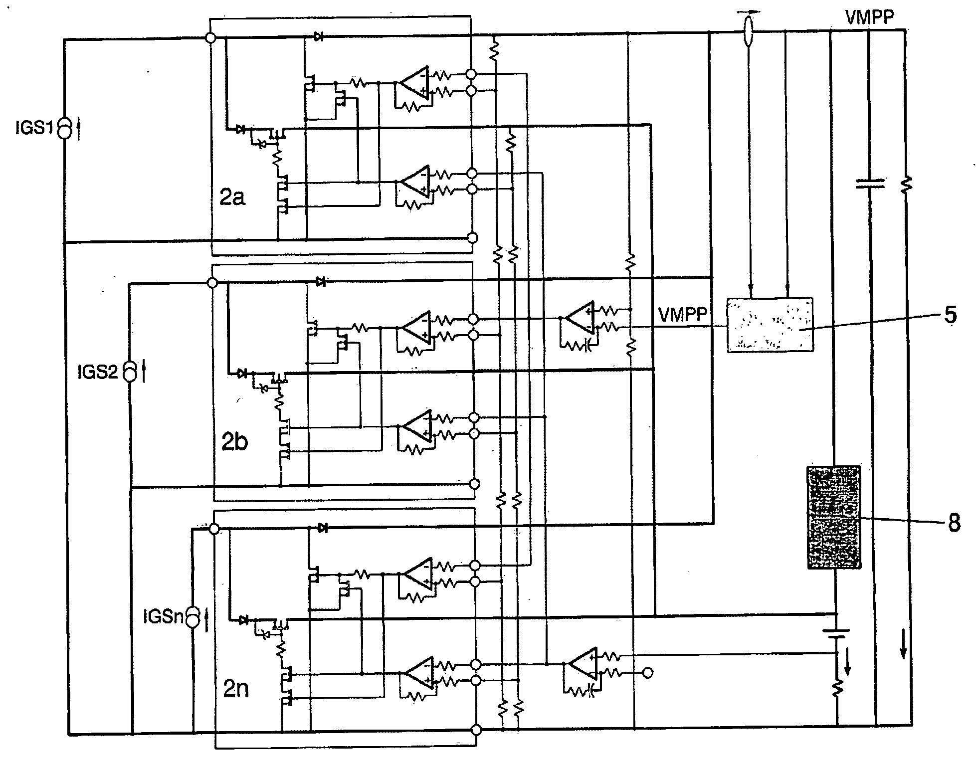
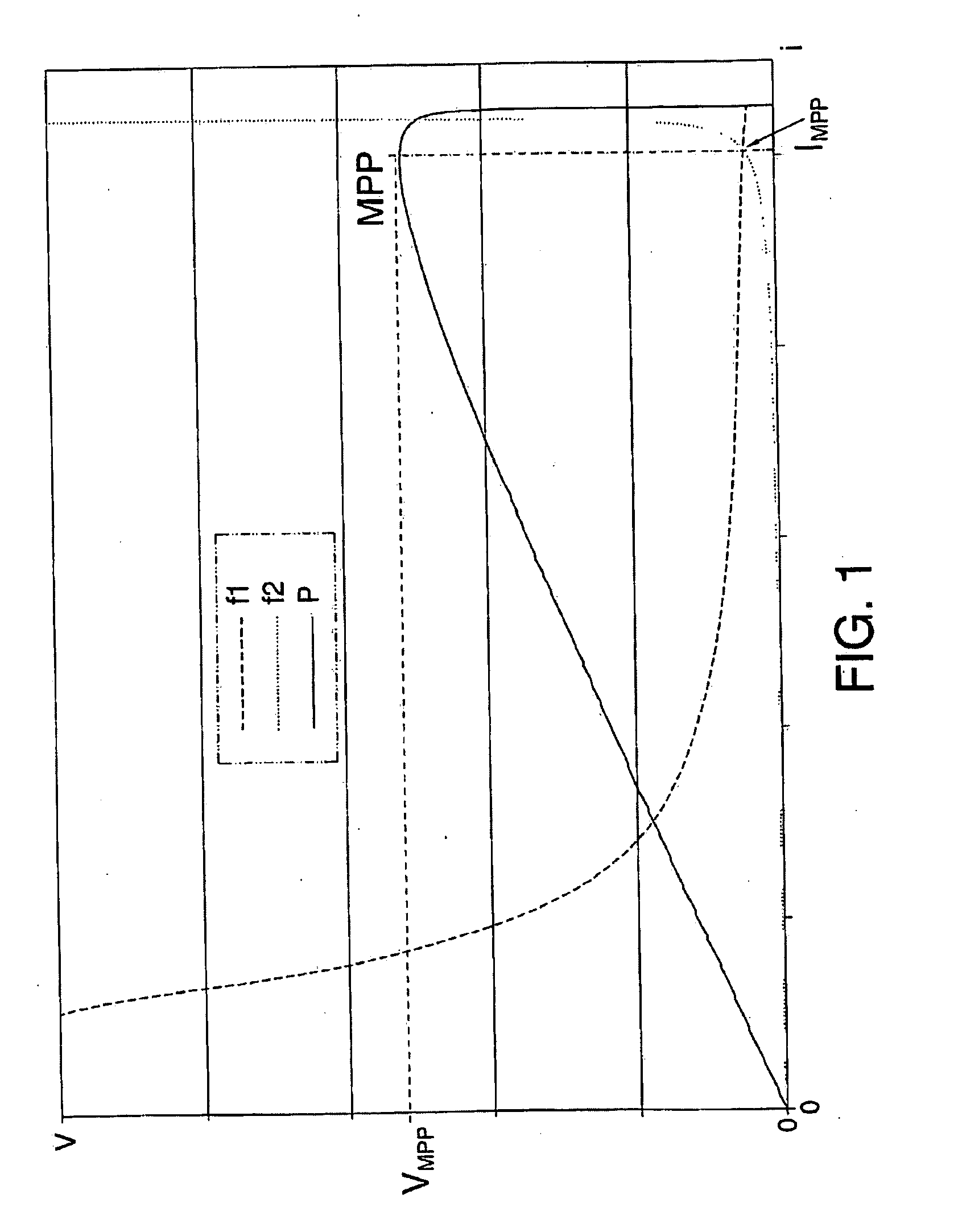
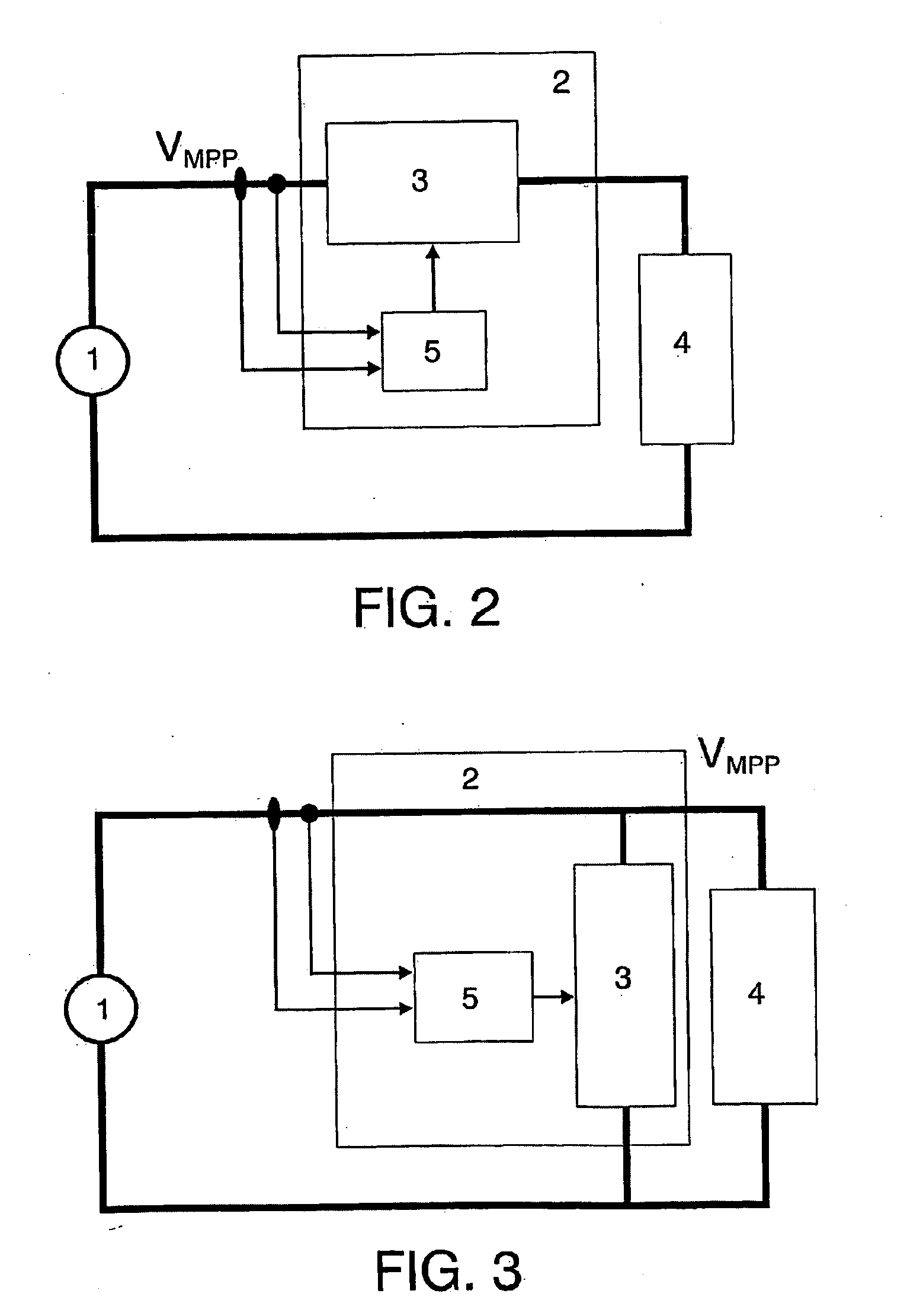
[0052]In view of the figures shown, a method for controlling the Point of Maximum Power for solar energy sources can be described as a possible practical option of embodiment of the invention, whose electric voltage characteristic (v) depending on the current (i) has a single Point of Maximum Power (PMP) corresponding to the maximum of the power function (P), P=vi, as is shown in FIG. 1. The source (1) is connected to a user loading network (4), by means of a power conditioning unit (2), as is illustrated in FIGS. 2 and 3, respectively, depending on whether the power regulator is configured with a power cell (3) in series or in parallel.

[0053]In said solar source (1) is disposed a plurality of photovoltaic cells distributed in a number of rows (n) and a number of columns (m). A calculation model (5) of the Point of Maximum Power (PMP) connected to the power cell (3) established a reference voltage (Vpmp), solving the equation:

vMPP=naLog(miSC-iMPPmiR)(2.21)

[0054]In order to determine...


PUM


Abstract

The invention is designed for continuous, rapid and effective monitoring of a solar or equivalent source in order successfully to arrange for it to operate at its point of maximum power (PMP) without interrupting the supply of electricity to users, with a conventional power-regulating structure of series or parallel type, governed by an independent module capable of calculating the voltage and current coordinates of said PMP (VPMP, IPMP) by applying an iterative algorithm and/or graphic methods. This module ideally requires only one measurement point, relating to the electrical characteristic, with the ambient conditions of said source, and as a result it delivers a reference signal, a continuous, stable voltage constantly representative of the evolution of the PMP, for the power regulator. In the event of the use of a power-regulating structure of S3R or ASR type, information about the PMP is immediate and requires no intermediate measurement point.

Description

RELATED APPLICATION[0001]This application is a 35 USC 371 national stage application of international application PCT / ES2007 / 000184 filed Mar. 30, 2007, which claims priority from Spain application P200600843 filed Mar. 31, 2006.OBJECT OF THE INVENTION[0002]The present invention has its main field of application in the industry destined to the design of electronic devices and, more specifically, within the sector of photovoltaic solar energy power systems.[0003]One object of the invention is to permit the energy source to work at its Point of Maximum Power (PMP), whenever this condition is required by the users, in a permanent manner without causing any discontinuity in the voltage it supplies.[0004]Likewise, an object of the invention is to provide a power control circuit for a solar generator with a high performance which continuously determines said Point of Maximum Power (PMP) quickly.BACKGROUND OF THE INVENTION[0005]Solar generators, such as those that comprise photovoltaic pan...

Claims


Application Information

Patent Timeline
IPC IPC(8): G05F1/67
CPCG05F1/67G05F1/10
Inventor CAPEL, ANTOINE
Owner MPPC TECH
Why Eureka
Try Eureka