Projector and Blasting Machine
a projector and blasting machine technology, applied in the field of projectors, can solve the problems of high grindability projectiles that cannot be used, metal impellers used, projectile damage, etc., and achieve the effects of simple structure, improved durability of projectiles, and reduced nois
- Summary
- Abstract
- Description
- Claims
- Application Information
AI Technical Summary
Benefits of technology
Problems solved by technology
Method used
Image

Examples
first embodiment
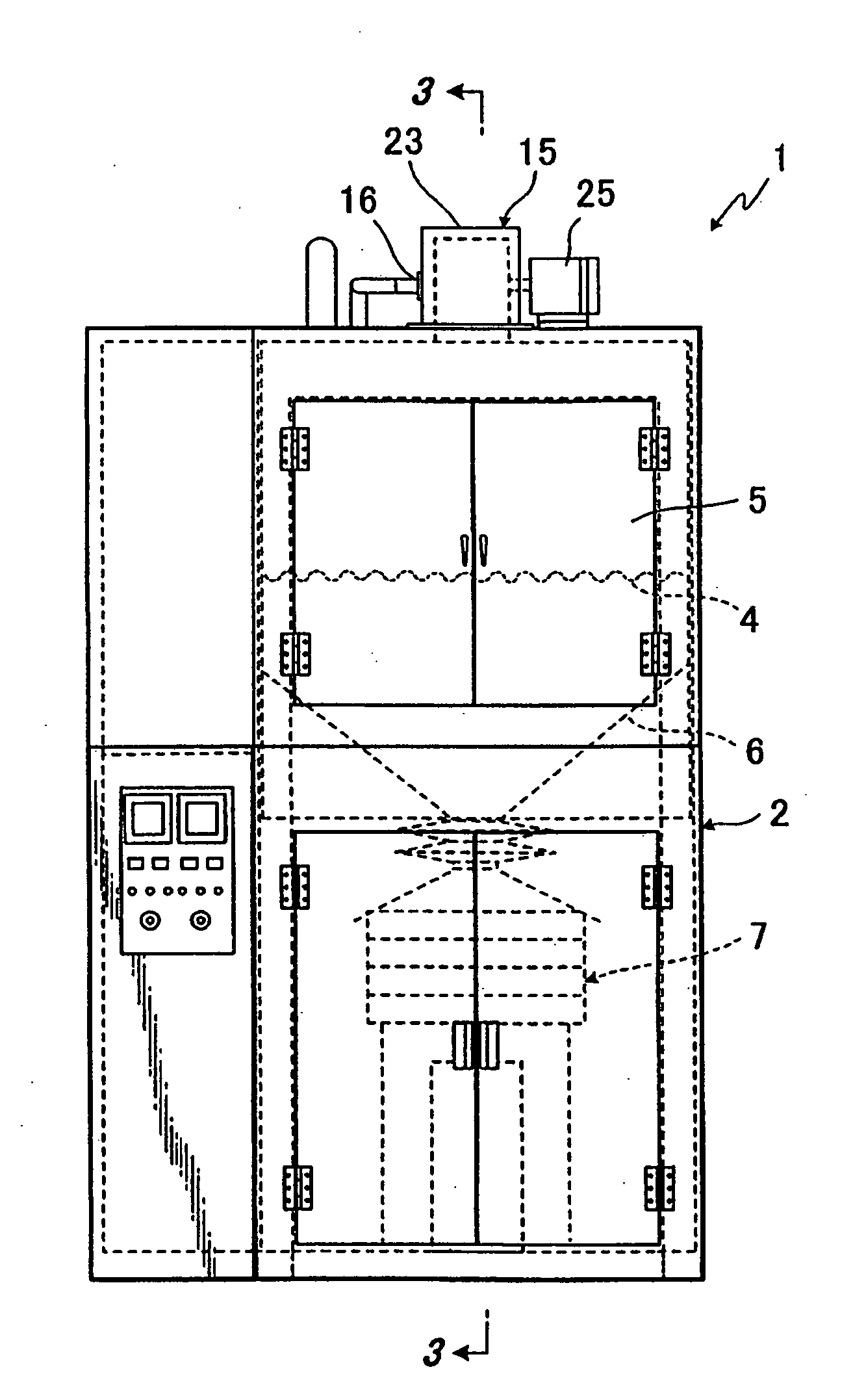
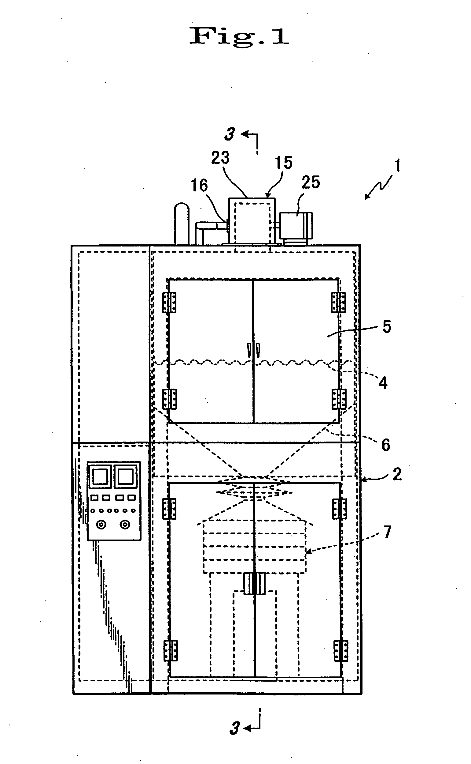
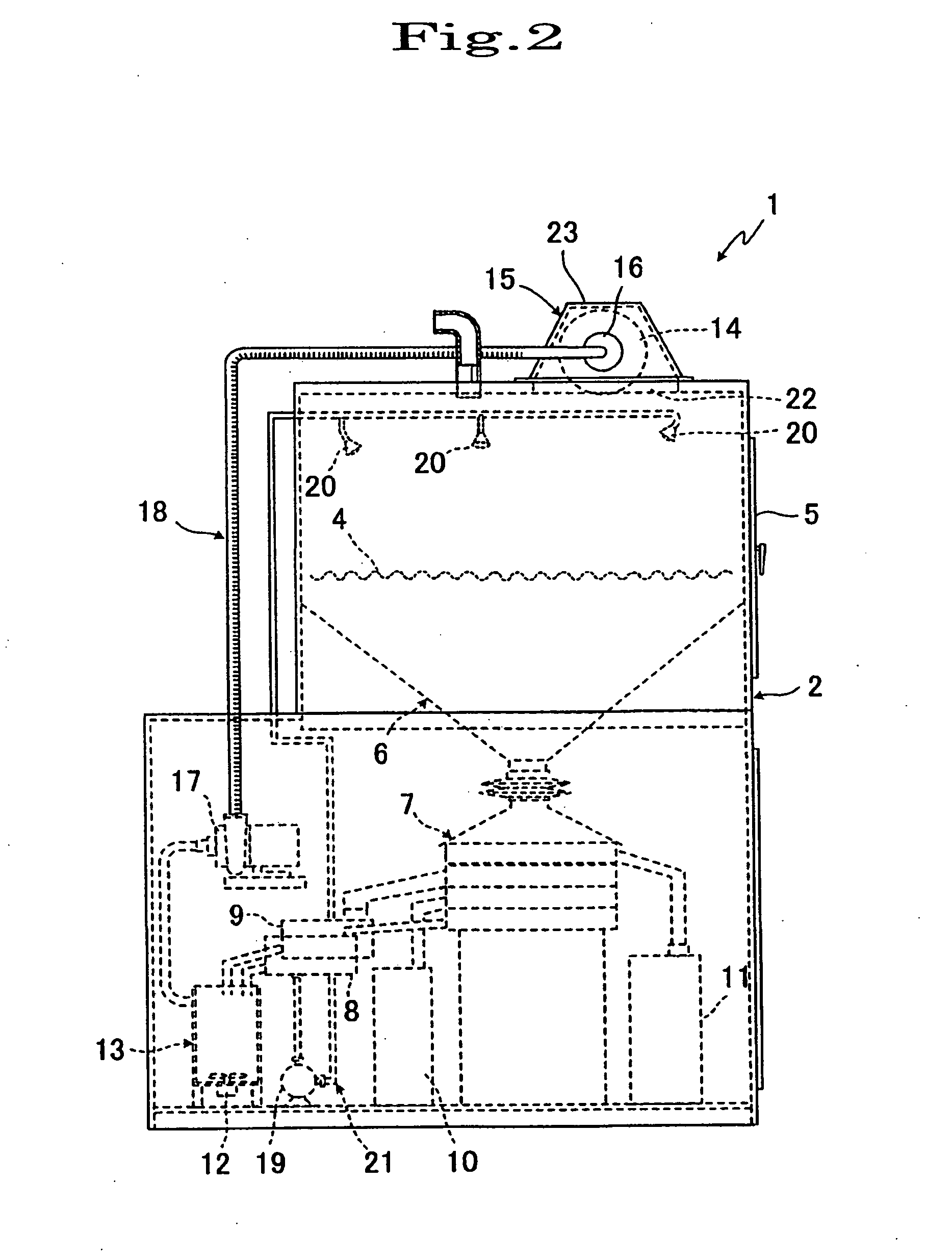
[0051]FIGS. 1 to 7 illustrate the present invention wherein reference numeral 1 is a shot blast machine which deburrs molded goods, treats the surface of molded goods and removes crud attached to the surface of the workpieces. The shot blast machine 1 is comprised of a housing 2; a table 4 in the form of a perforated plate or a mesh, as a support for a workpiece 3, installed into an upper portion of the housing 2; an openable door 5 attached to the housing 2 enabling placing the workpiece 3 onto and removing the workpiece 3 from the table 4; a separator 7 with a vibrating screen below the table 4 in the housing 2 and communicating with the table 4 through the hopper 6; a liquid tank 8 provided with liquid such as water, cleaning liquid or the like separated out by the separator 7 therein, a projectile tank 9 provided the projectile therein, a small particle tank 10 having small particles therein, and a large particle tank 11 provided large particles therein; a mixing tank 13 having ...
second embodiment
[0060]the present invention is shown in FIGS. 8 and 9 and is distinguished from the first embodiment by the fact that a high abrasion-resistant rubber sheet 39 is fixed to an inner wall surface of the wheel cover 23 by adhering, coating and the like in order to blast the projectile-mixed liquid to the workpiece 3 on the table from the side and upper portion of the housing 2; and the projector 15 is replaced from two projectors 15A, 15A which adhered or coated a high abrasion-resistant rubber 41 on a surface of an impeller body 40 made of metal.
[0061]A shot blast machine 1A in this way according to the third embodiment has similar advantages to that according to the first embodiment.
[0062]A third embodiment of the present invention is shown in FIGS. 10 to 12 and is distinguished from the first embodiment by the fact that a belt conveyor 31 as a supporting device is used, forming in the shape of a L-letter, capable of holding the workpiece 3 and agitating it. A shot blast machine 1B w...
fifth embodiment
[0067]A shot blast machine 1D in this way may be composed.
PUM
 Abstract
Description
Claims
Application Information
PatSnap Eureka turns technology decisions into work you can execute. Powered by our Innovation Knowledge Graph, it runs expert workflows across engineering, life sciences, materials and intellectual property. Get your review-ready output in minutes.


