Cold-start reliability and reducing hydrocarbon emissions in a gasoline direct injection engine

a technology of gasoline direct injection and cold-start reliability, which is applied in the direction of electrical control, process and machine control, instruments, etc., can solve the problems of reducing fuel economy, affecting the reliability of cold-starting, and affecting the efficiency of cold-starting

Inactive Publication Date: 2010-07-15
FORD GLOBAL TECH LLC
View PDF25 Cites 16 Cited by
  • Summary
  • Abstract
  • Description
  • Claims
  • Application Information

AI Technical Summary

Benefits of technology

[0012]In short, starting on less than all cylinders reduces the overall need for overfueling during cold start at low engine temperatures. Reduced or controlled manifold air pressure starts have a double effect of reducing the fueling requirement while increasing the fraction of fuel evaporated. Enacted separately or together, both of these actions may have further advantageous effects.

Problems solved by technology

At cold start, however, and especially when the engine temperature is low, adequate vaporization of the fuel may be difficult to achieve.
However, various disadvantages are associated with overfueling a DI engine during cold start conditions.
A first problem relates to torque control during the run-up period, viz., the period after the engine starts but before a stable idle is achieved.
If, as a result of cold-start overfueling, a significant amount of unvaporized fuel accumulates in the combustion chambers of an engine, an unwanted surge of torque may occur during run-up, when the fuel finally vaporizes and is combusted.
Some engine systems are configured to intentionally run up the engine speed to clear out excess fuel left over from the start up, but this strategy is inelegant and degrades fuel economy.
A second problem relates to emissions-control performance.
Excessive hydrocarbon emissions may result from exhaust-system catalysts being underheated, from deliberate enrichment of the pre-ignition air / fuel mixture to enhance ignition reliability (as discussed above) and from unreliable ignition, i.e., misfire, occurring during the first few expansion strokes.
If misfire occur at this time, multiple and / or extended cranking attempts may be necessary to start the engine, further worsening emissions-control performance.
A third problem relates to the ability of the engine's high-pressure pump to provide the necessary initial rate of fueling to all of the combustion chambers of the engine.
This countermeasure may suffer from a number of drawbacks, however.
First, cranking periods are necessarily extended because ignition is delayed until the fuel rail is fully pressurized.
Second, the rapid decrease in fuel-rail pressure when the fuel is finally delivered may cause injection-mass control difficulties, resulting in difficult or failed starting.
Third, the accumulated fuel-rail pressure may be exhausted before the first firing occurs, should firing occur at all.
As a result, multiple and / or extended cranking attempts may be necessary to start the engine.
A potential disadvantage of this countermeasure is that some combustion chambers in an engine may be prone to misfire due to degradation of one or more components—fuel injectors, valve seals, spark plugs, for example.
If a combustion chamber prone to misfire is among those included for fueling in a starting sequence in which only a limited number of combustion chambers are fueled, the engine may not develop adequate torque to start.
Thus, a potentially useful additional countermeasure that might otherwise be modified to address the fuel-delivery and emissions-control problems described above is compromised by misfire during cranking.
However, none of the approaches cited above address the effect on emissions-control performance of misfire in the first fueled combustion chamber during start-up.
Providing consistency over a wide range of cold-start conditions may further reduce the engineering and testing required to find a workable fueling formula and / or protocol.

Method used


Image

  • Cold-start reliability and reducing hydrocarbon emissions in a gasoline direct injection engine
  • Cold-start reliability and reducing hydrocarbon emissions in a gasoline direct injection engine
  • Cold-start reliability and reducing hydrocarbon emissions in a gasoline direct injection engine

Examples


Embodiment Construction

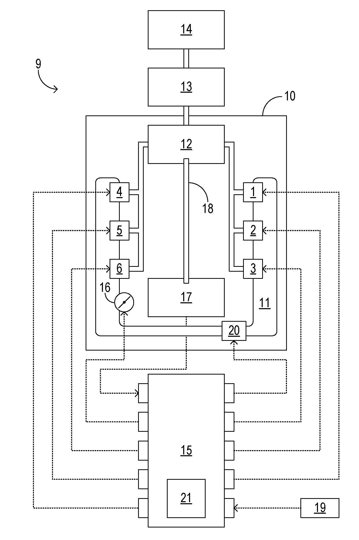
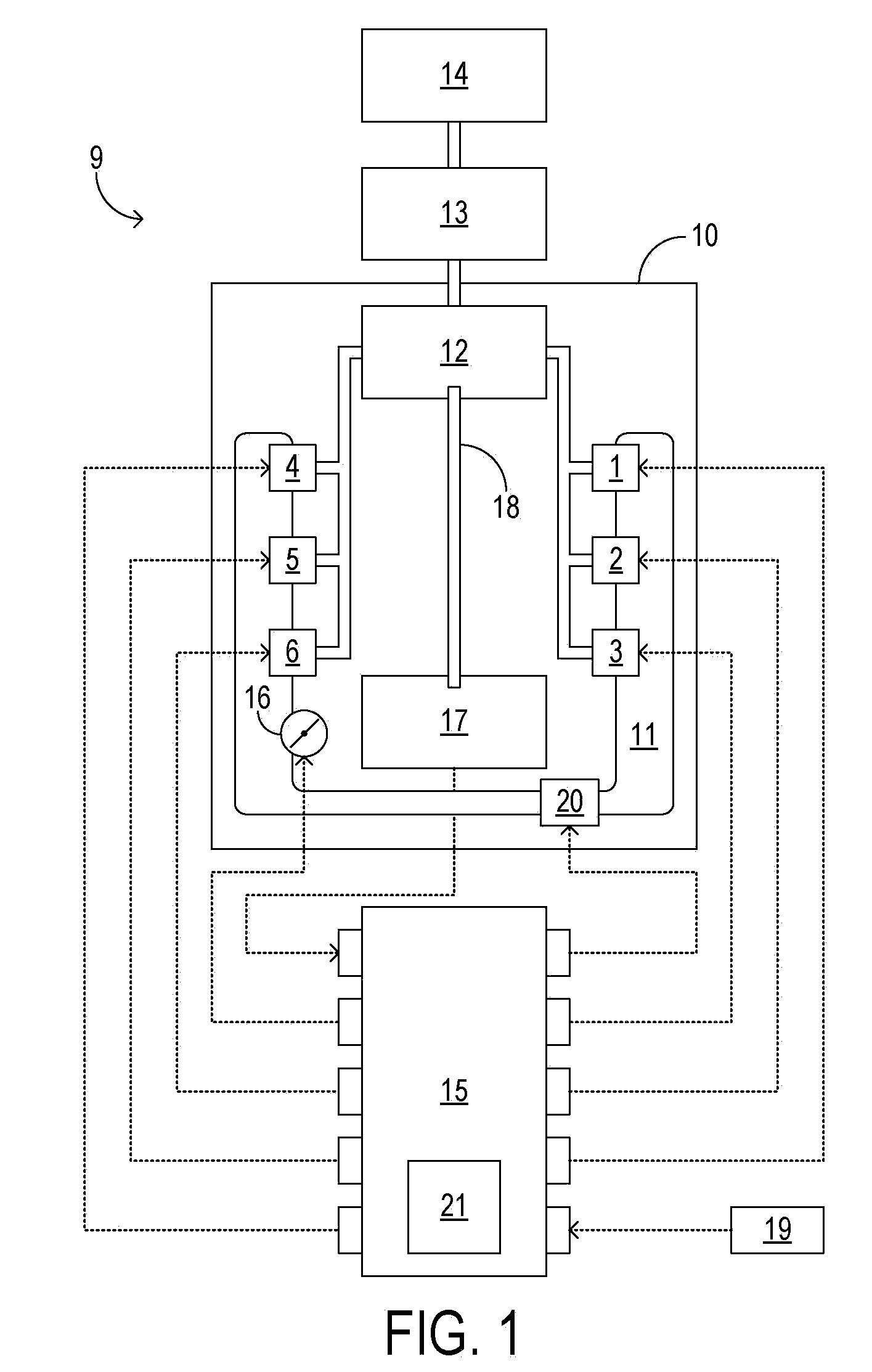
[0020]FIG. 1 shows example engine system 9 in schematic detail. The engine system includes GDI engine 10. In the illustrated embodiment, the engine comprises six combustion chambers arranged in a V-6 configuration. The combustion chambers are provided intake air via intake manifold 11 and are provided fuel via fuel injectors 1-6, which are directly coupled to the combustion chambers. In other embodiments equally consistent with this disclosure, the engine may have a different configuration and / or a different number of combustion chambers and fuel injectors.

[0021]Continuing in FIG. 1, each of the fuel injectors 1-6 is provided pressurized fuel via high-pressure pump 12, which may be an engine-driven pump. In the illustrated embodiment, the high-pressure pump is mechanically coupled to engine 10. The high pressure pump is supplied fuel by lift pump 13, which draws fuel from fuel tank 14. Further, each of the fuel injectors is operatively coupled to, and configured to receive a control...


PUM


Abstract

A method for starting an engine of a motor vehicle, the engine having an intake manifold, an intake throttle controlling admission of air into the intake manifold, and a plurality of combustion chambers communicating with the intake manifold, the method comprising providing a reduced pressure of air in the intake manifold prior to delivering fuel or spark to the engine, the reduced pressure of air responsive to a temperature of the engine; delivering fuel to one or more of the plurality of combustion chambers in an amount based on the reduced pressure of air; and delivering spark to the one or more combustion chambers to start the engine.

Description

TECHNICAL FIELD[0001]The present application relates to the field of motor-vehicle engine systems and more particularly to cold-start reliability and emissions control in motor-vehicle engine systems.BACKGROUND AND SUMMARY[0002]Reliable air / fuel ignition in a liquid-fueled, direct-injection (DI) engine depends on adequate vaporization of fuel in the engine's combustion chambers. At cold start, however, and especially when the engine temperature is low, adequate vaporization of the fuel may be difficult to achieve. Further, the temperatures where vaporization becomes an issue may increase with decreasing volatility of the fuel (e.g., regular gasoline, premium gasoline, summer gasoline, alcohol-based fuels, diesel fuel, in order of decreasing volatility). To compensate for inadequate vaporization of liquid fuels at low engine temperatures, a fuel-injection control unit may be configured to adjust the rate of fuel-injection in response to engine temperature, and to fuel the engine's co...

Claims


Application Information

Patent Timeline
Patent Type & Authority Applications(United States)
IPC IPC(8): F02D41/06
CPCF02D41/0002F02D41/0025F02D2200/1015F02D2200/0406F02D41/064
Inventor SURNILLA, GOPICHANDRAPURSIFULL, ROSS DYKSTRA
Owner FORD GLOBAL TECH LLC
Why Eureka
Try Eureka