
System and method for redundancy-protected aggregates

a technology of aggregates and redundancy protection, applied in the field of storage systems, can solve problems such as significant number of disks, aggregate failure, and loss of connectivity

Active Publication Date: 2010-07-15
NETWORK APPLIANCE INC
View PDF99 Cites 64 Cited by
  • Summary
  • Abstract
  • Description
  • Claims
  • Application Information

AI Technical Summary

Benefits of technology

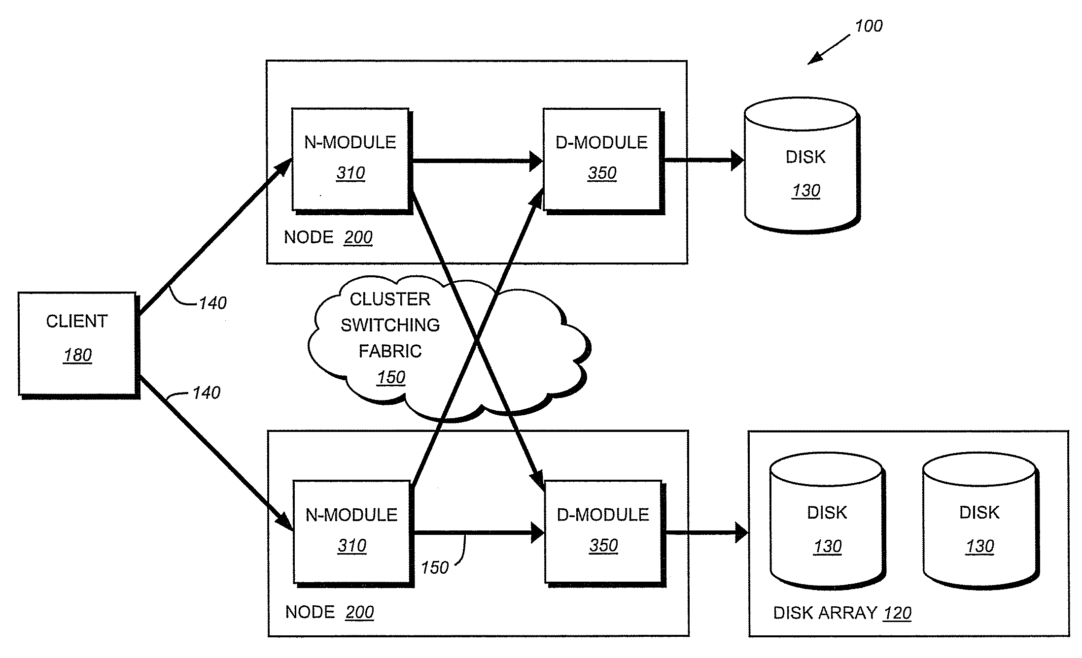
[0008]The present invention overcomes the disadvantages of the prior art by providing a storage architecture that implements redundancy-protected aggregates across a plurality of nodes interconnected as a cluster. Each node is embodied as a storage system that is primarily responsible for servicing a locally attached aggregate. Moreover, each storage system is associated with a designated “partner” storage system in the cluster that is configured to service the aggregate in the event of a failure. That is, redundancy-protected aggregates are configured so that if a storage system (e.g., its attached aggregate) fails, the storage system (or its partner) can reconstruct the data which would be otherwise in-accessible from the failed aggregate.

Problems solved by technology

Aggregates can fail for a number of reasons, including lost connectivity, failure of a significant number of disks within a volume and / or aggregate, etc.
When an aggregate fails, clients may be unable to access the data contained on the failed aggregate.
If the storage system itself fails, however, then the data stored on the served aggregate is no longer accessible to the client, thus resulting in aggregate failure.
Mirroring of an aggregate typically requires complete duplication of storage system resources, including storage devices, resulting in an inefficient use of storage space (for example by utilizing half of the overall space consumed on a storage system) and substantial operating costs.
Additionally, the response time in some mirrored systems, e.g., a mirrored synchronous storage system, may be especially slow because such systems store data in both mirrors before the systems can respond to clients that the data has been persistently stored.

Method used


Image

  • System and method for redundancy-protected aggregates
  • System and method for redundancy-protected aggregates
  • System and method for redundancy-protected aggregates

Examples


Embodiment Construction

[0028]According to one or more embodiments described herein, redundancy-protected aggregates are configured so that if one aggregate of a clustered storage system fails, the storage system (or its partner) can reconstruct the data stored on the failed aggregate, which would be otherwise inaccessible by the other storage systems of the cluster. For instance, striped aggregates illustratively comprise a plurality of constituent aggregates. Redundancy information, e.g., parity, is distributed among the constituent aggregates based upon the number of constituent aggregates in the cluster and arbitrary fixed-size “parity regions,” wherein within each region only one constituent aggregate is assigned as a parity owner. During a “normal” mode of operation, data is written to an aggregate and parity computed for the data is written to a corresponding parity owner, e.g., based on the parity region of the written data and the constituent aggregates of the striped aggregates. Upon failure of a...


PUM


Abstract

The present invention provides a system and a method for utilizing a parity protection module to back up data on striped aggregates. Specifically, the system computes party data for data stored at a particular location of each of a plurality of constituent aggregates, and stores the parity on one of the constituent aggregates that is a parity owner for that particular location of data. In the event one of the constituent aggregates fails, new data may still be accessed by the system (the striped aggregates), both to write new data, and to read data stored on the failed aggregate. In particular, the parity protection module allows clients to read data from a failed aggregate by running a reverse parity computation, which may also be used to restore the data to the failed aggregate.

Description

FIELD OF THE INVENTION[0001]The present invention is directed to storage systems, and, in particular, to redundancy-protected aggregates on one or more storage systems.BACKGROUND OF THE INVENTION[0002]A storage system typically comprises one or more storage devices into which information may be entered, and from which information may be obtained, as desired. The storage system includes a storage operating system that functionally organizes the system by, inter alia, invoking storage operations in support of a storage service implemented by the system. The storage system may be implemented in accordance with a variety of storage architectures including, but not limited to, a network-attached storage environment, a storage area network and a disk assembly directly attached to a client or host computer. The storage devices may be persistent electronic storage devices, such as flash memories, but are typically disk drives organized as a disk array, wherein the term “disk” commonly descr...

Claims


Application Information

Patent Timeline
IPC IPC(8): G06F11/14G06F11/20G06F12/00
CPCG06F11/1076G06F2211/1045G06F2211/1028
Inventor JERNIGAN,, IV, RICHARD P.HYER,, JR., ROBERT WYCKOFFKAZAR, MICHAEL L.NYDICK, DANIEL S.
Owner NETWORK APPLIANCE INC
Learn More