
Methods for increasing carbon dioxide content in gas turbine exhaust and systems for achieving the same

a technology of gas turbine exhaust and carbon dioxide content, which is applied in the direction of hot gas positive displacement engine plants, machines/engines, jet propulsion plants, etc., can solve the problems of generating considerable amounts of solid waste, affecting the performance of the engine,

Inactive Publication Date: 2010-07-22
GENERAL ELECTRIC CO
View PDF16 Cites 127 Cited by
  • Summary
  • Abstract
  • Description
  • Claims
  • Application Information

AI Technical Summary

Problems solved by technology

Power plants also discharge potentially harmful effluents into surface and ground water, and generate considerable amounts of solid wastes, some of which may be hazardous.
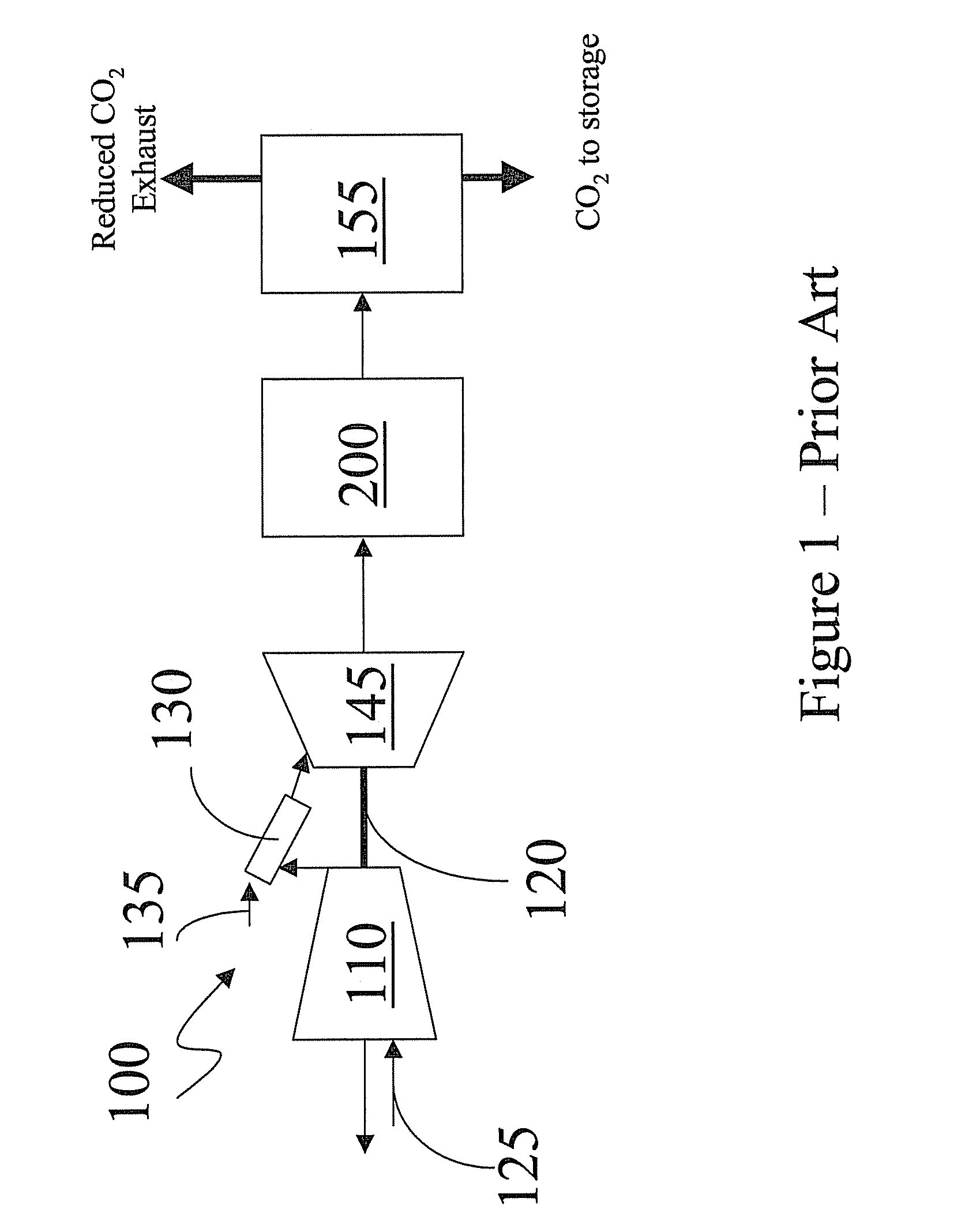
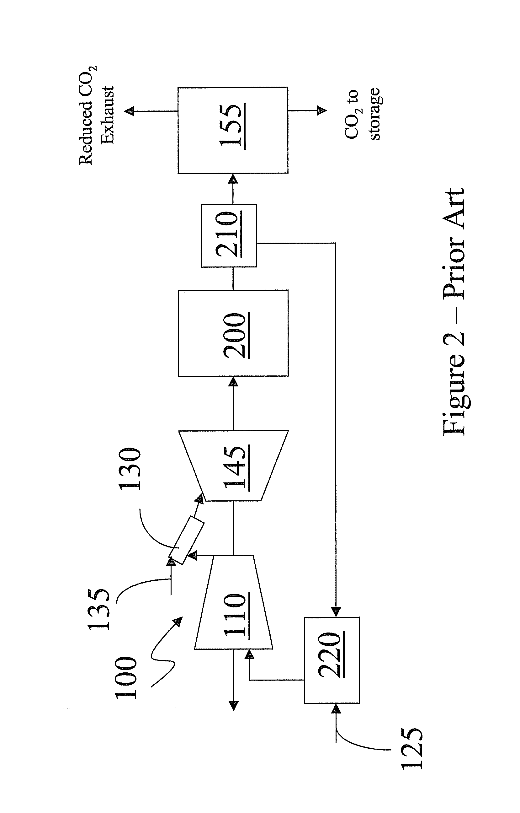
The low concentration of CO2 in the exhaust gas stream and the corresponding increased concentration of oxygen lead to challenges for CO2 capture systems employed in NGCC plants.
CO2 capture systems face a plurality of challenges when operated in high oxygen and therefore low CO2 concentration exhaust gas streams.
The low concentration of CO2 causes the use of large and expensive equipment to be used to handle the volume of exhaust gases.
In addition, the low CO2 concentration decreases the thermal efficiency of the CO2 separation.
The high oxygen concentration will cause damage to CO2 capture systems that happen to be sensitive to oxidation.
This leads to a reduction in efficiency as a result of downtime to facilitate maintenance of the amine scrubbing system.
This increases the operating cost of the plant.
Oxygen is very damaging to sequestration systems, and cannot be allowed in any appreciable concentration in the CO2 stream that is being sequestered.

Method used


Image

  • Methods for increasing carbon dioxide content in gas turbine exhaust and systems for achieving the same
  • Methods for increasing carbon dioxide content in gas turbine exhaust and systems for achieving the same
  • Methods for increasing carbon dioxide content in gas turbine exhaust and systems for achieving the same

Examples


Embodiment Construction

[0016]The following detailed description of preferred embodiments refers to accompanying drawings, which illustrate specific embodiments. Other embodiments having different structures and operations do not depart from the scope of the subject matter disclosed herein.

[0017]Certain terminology is used herein for the convenience of the reader only and is not to be taken as a limitation on the scope of the invention. For example, words such as “upper,”“lower,”“left,”“right,”“front”, “rear”“top”, “bottom”, “horizontal,”“vertical,”“upstream,”“downstream,”“fore”, “aft”, and the like; merely describe the configuration shown in the Figures. Indeed, the element or elements of an embodiment of the subject matter disclosed herein may be oriented in any direction and the terminology, therefore, should be understood as encompassing such variations unless specified otherwise.

[0018]It is to be noted that as used herein, the terms “first,”“second,” and the like do not denote any order or importance,...


PUM


Abstract

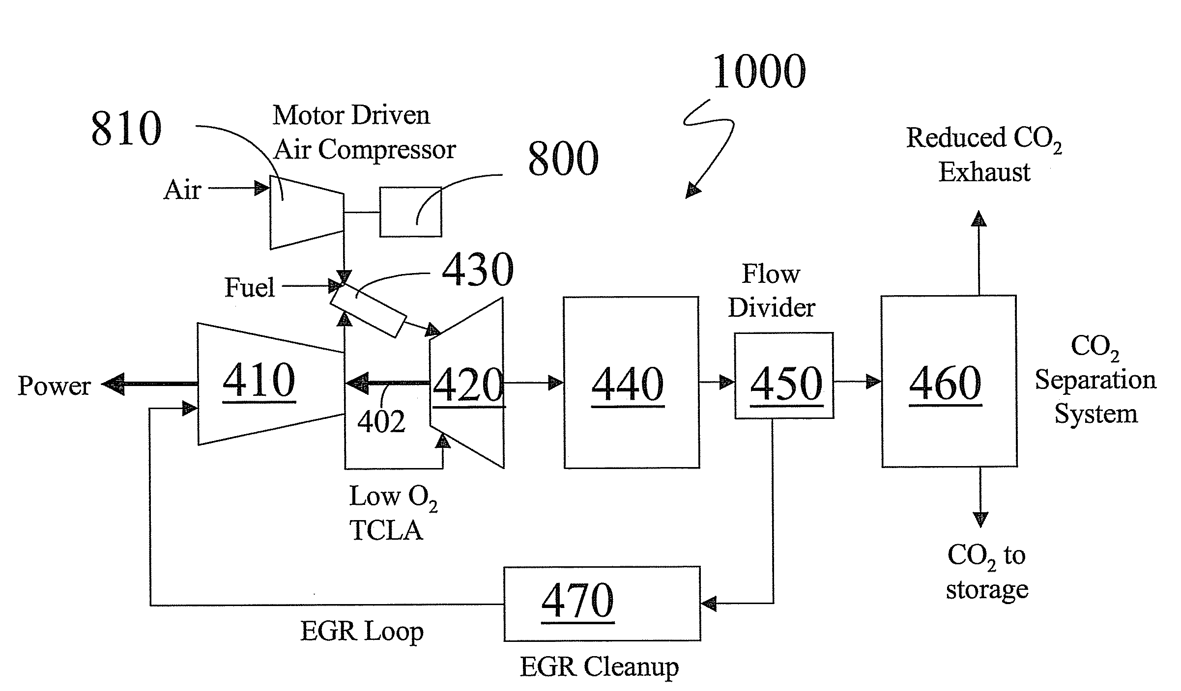
Disclosed herein is a system comprising a first compressor; the compressor being operative to compress air; a turbine; the turbine being disposed downstream of the first compressor; the turbine being operative to combust a hydrocarbon fuel along with compressed air from the first compressor to produce an exhaust gas stream; and a second compressor; the second compressor being disposed downstream of the turbine; the second compressor being operative to compress the exhaust gas stream and to recycle the compressed exhaust gas stream to the turbine. Disclosed herein is a method comprising compressing air in a first compressor; combusting the air along with a hydrocarbon fuel in a turbine; generating an exhaust gas stream from the turbine; compressing the exhaust gas stream in a second compressor; recirculating the compressed exhaust gas stream to the turbine; separating carbon dioxide from the exhaust gas stream; and storing the carbon dioxide.

Description

BACKGROUND OF THE INVENTION[0001]This disclosure relates to methods for increasing the carbon dioxide (CO2) content in gas turbine exhaust gas streams and systems for achieving the same.[0002]Environmental pollution stemming from fossil-fueled power plants is of worldwide concern. Power plants emit air pollutants that may be toxic, e. g., toxic metals and polyaromatic hydrocarbons; precursors to acid rain, e.g., sulfur oxides (SOx) such as sulfur dioxide (SO2) and nitrogen oxides (NOx); precursors to ozone such as for example, NO2 and reactive organic gases; particulate matter; and greenhouse gases, notably CO2. Power plants also discharge potentially harmful effluents into surface and ground water, and generate considerable amounts of solid wastes, some of which may be hazardous.[0003]Natural gas fired gas turbine combined cycle (NGCC) power plants emit lower quantities of CO2 per megawatt hour than pulverized coal fired power plants. This is due to the lower percentage of carbon i...

Claims


Application Information

Patent Timeline
IPC IPC(8): F02C3/34
CPCF02C1/007Y02E20/16F02C3/22F02C1/08
Inventor DRAPER, SAMUEL DAVID
Owner GENERAL ELECTRIC CO
Learn More