Automotive engine bearing

a bearing and engine technology, applied in the direction of bearing unit rigid support, machines/engines, mechanical equipment, etc., can solve the problems of high cost and high volume of conventional block-and-cap construction, high cost and high cost of high-volume production, and the material which is suitable for fracturing process is often not optimal in terms of physical properties, and achieves excellent integrity, long service life, and corrosion resistance. excellent

Active Publication Date: 2010-07-22
FORD GLOBAL TECH LLC
View PDF10 Cites 9 Cited by
  • Summary
  • Abstract
  • Description
  • Claims
  • Application Information

AI Technical Summary

Benefits of technology

[0013]It is an advantage of an automotive engine bearing according to the present invention that an economical production process including fracturing of the main bearing caps from the cylinder block may be employed, while at the same time providing bearing structures having excellent integrity and the ability to provide long service life in real-world automotive conditions.
[0014]It is another advantage according to an automotive engine bearing system according to the present

Problems solved by technology

Unfortunately, the necessity for separate bearing caps, produced by a completely separate manufacturing process, as well as the necessity for dowels and other devices to maintain the main bearing caps in proper alignment during the assembly of the engine and subsequent reassembly during service operations, renders the conventional block-and-cap construction both expensive and a burden to execute in high volume production.
Unfortunately, materials which are suitable for use with the fracturing process are frequently not optimal in terms of their physical properties.
On point, it has been determined that a good deal of distortion occurs within main bearing bores in a firing engine when the fractured bearing caps are held in place with two

Method used


Image

  • Automotive engine bearing
  • Automotive engine bearing
  • Automotive engine bearing

Examples


Embodiment Construction

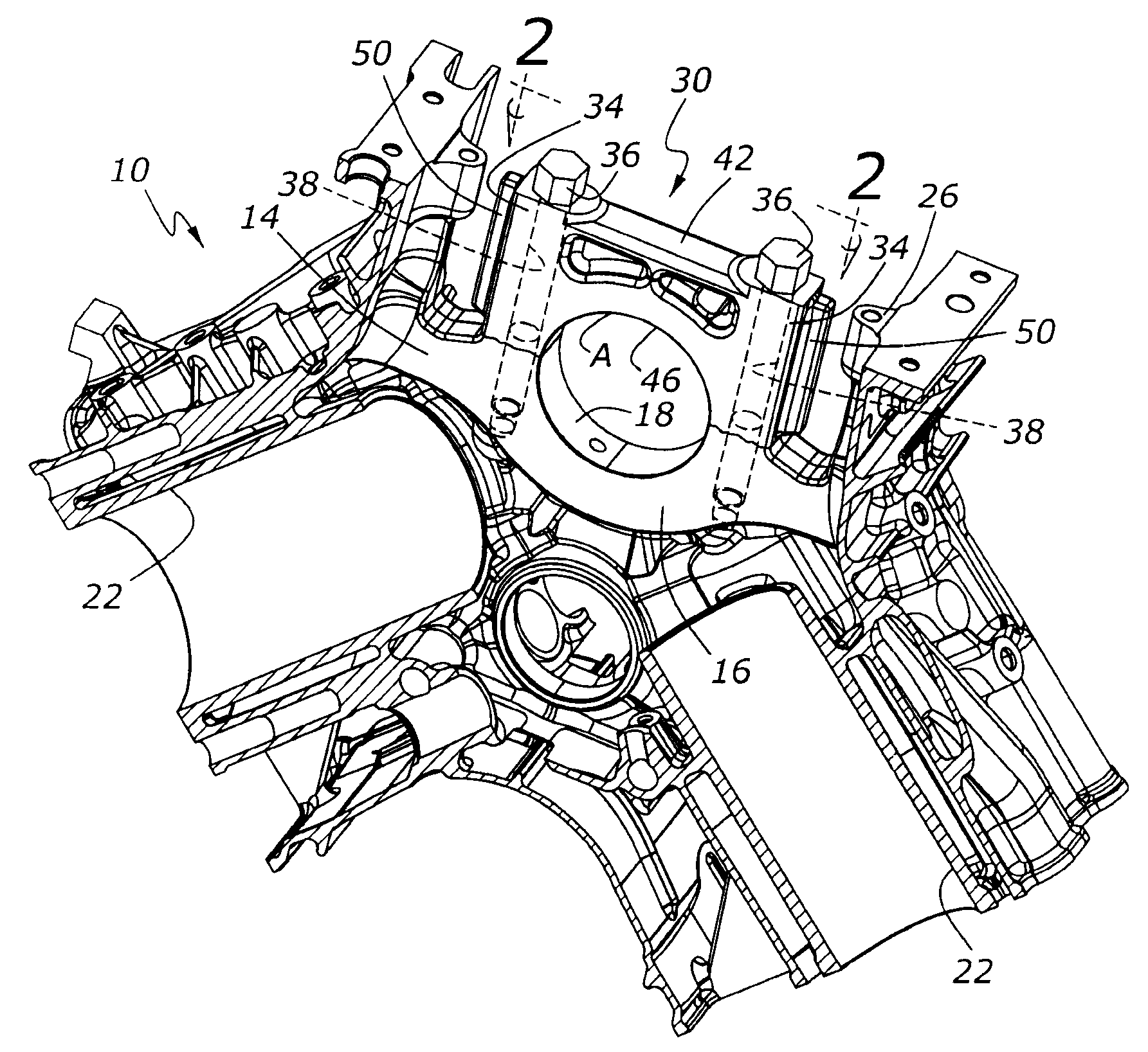
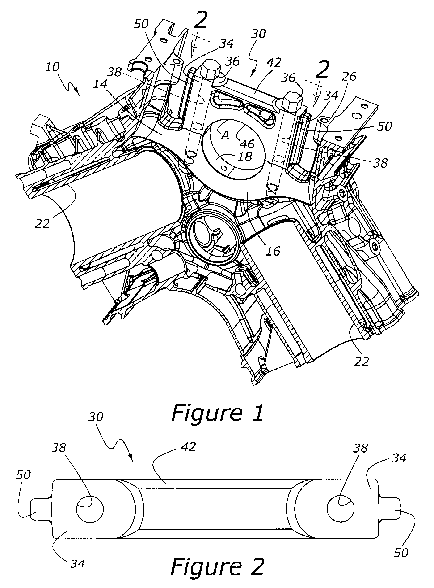
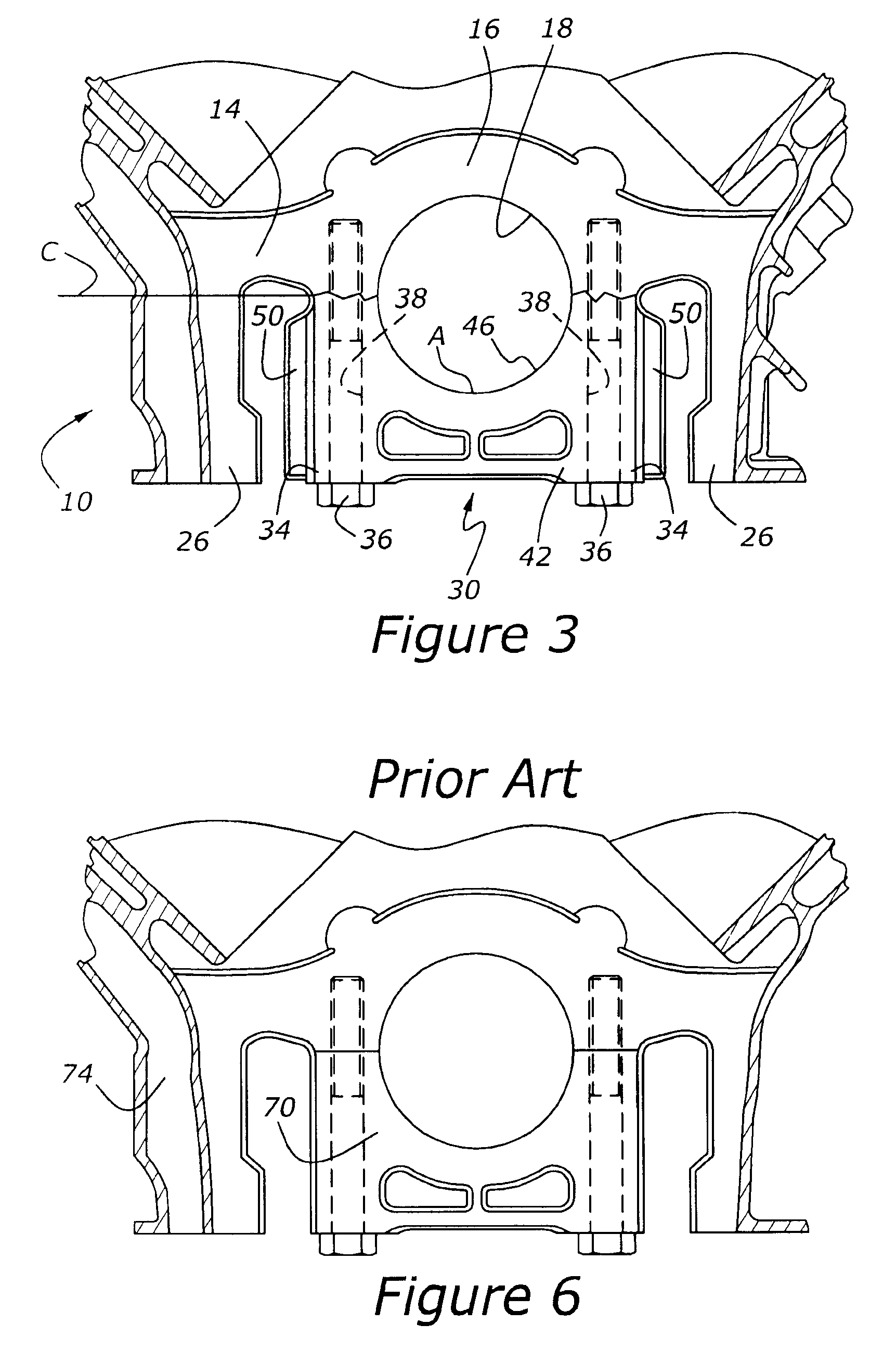
[0023]Referring to the Figures, wherein like numerals indicate like or corresponding parts throughout the several views, as shown in FIG. 1, cylinder block 10 includes a bearing base, 14, including a first bearing segment 16, having a semi-circular bore 18 formed therein. A bearing cap, 30, is mounted to bearing base 14 with cap screws 36. Cap screws 36 pass through bores 38 formed within fastener towers 34, which extend from base 14 to the hexagonal heads of cap screws 36. A second bearing segment, 42, extends between fastener towers 34 and includes a semi-circular bore, 46. Taken together, semi-circular bore 46 and semi-circular bore 18 define a circular bore for an engine crankshaft (not shown). Although only a single main bearing is illustrated in FIG. 1, those skilled in the art will appreciate in view of this disclosure that most engines will utilize at least two such main bearings, if not five, or six, or more. This detail is committed to those wishing to employ the present i...


PUM


Abstract

A bearing for an automotive engine includes a base having a first bearing segment formed therein, and a bearing cap removably mounted to the base, with the bearing cap including fastener towers in contact with the base. A second bearing segment extends between the fastener towers. A number of non-contact stiffening ribs extend parallel to the fastener towers. The stiffening ribs are attached to outboard portions of the fastener towers. The stiffening ribs cause the bearing cap to avoid excessive flexing and distortion, while at the same time avoiding fretting corrosion which would occur were the clamp loads of the cap to the base be reduced by materially increasing the size of the fastener towers.

Description

CROSS REFERENCE TO RELATED APPLICATIONS[0001]None.BACKGROUND OF THE INVENTION[0002]1. Field of the Invention[0003]The present invention relates to a bearing construction which is particularly useful for mounting a crankshaft within an internal combustion engine.[0004]2. Related Art[0005]Internal combustion engines, particularly automotive internal combustion engines, typically use main bearing architectures in which a crankshaft is mounted to the cylinder block of the engine with bearing caps held in place with threaded fasteners. Conventional construction methods require that the cylinder block be machined separately to accept the bearing caps, which are themselves subject to separate manufacturing processes. Once both parts are machined, the cylinder block and bearing caps are joined together and then the main bearing bores are further machined, typically with boring and honing operations. Unfortunately, the necessity for separate bearing caps, produced by a completely separate ma...

Claims


Application Information

Patent Timeline
IPC IPC(8): F16C35/00F02F7/00
CPCF02F7/0053F16C35/00F16C9/02
Inventor PALAZZOLO, CHRISTOPHER KELLYSELF, DARYL
Owner FORD GLOBAL TECH LLC
Why Eureka
Try Eureka