
Multi-point tethering and stability system and control method for underwater current turbine

a multi-point, stability technology, applied in the direction of electric generator control, special-purpose vessels, vessel construction, etc., can solve the problems of engineering challenges of deploying towers in deeper waters, underwater construction costs, etc., and achieve simple control, provide stability, and provide stability

Inactive Publication Date: 2010-07-22
AQUANTIS
View PDF8 Cites 47 Cited by
  • Summary
  • Abstract
  • Description
  • Claims
  • Application Information

AI Technical Summary

Benefits of technology

[0027]An advantage of the invention is that neither buoyancy of the strut or the device nor a degree of lift from a wing is required to be variable to achieve the objectives of the invention. Furthermore, no wing is required, and in particular, no wing with a variable lift is required since a positive buoyancy is provided by the device and the strut.
[0028]The invention has the advantage that it provides stability in all degrees of freedom but provides the flexibility of twisting about a vertical axis (moving in yaw) in the current flow for directional changes.
[0029]The invention has the advantage that it provides stability in all degrees of freedom but allows the flexibility of depth adjustment for velocity changes (moves in pitch and is depth adjustable by simple controls).
[0030]The invention has the advantage that it provides for a remote command to effect rising to the surface for servicing and for submerging to depth to avoid severe weather-induced flow disruption.
[0031]The invention has the advantage that it provides stability if the counter-rotating torques generated by the blades significantly differ.
[0032]The invention has the advantage that it provides stability if the flow sharply decreases or increases in velocity.

Problems solved by technology

The disadvantages of this type of design are the underwater construction costs and the engineering challenges of deploying towers in deeper waters.

Method used


Image

  • Multi-point tethering and stability system and control method for underwater current turbine
  • Multi-point tethering and stability system and control method for underwater current turbine
  • Multi-point tethering and stability system and control method for underwater current turbine

Examples


Embodiment Construction

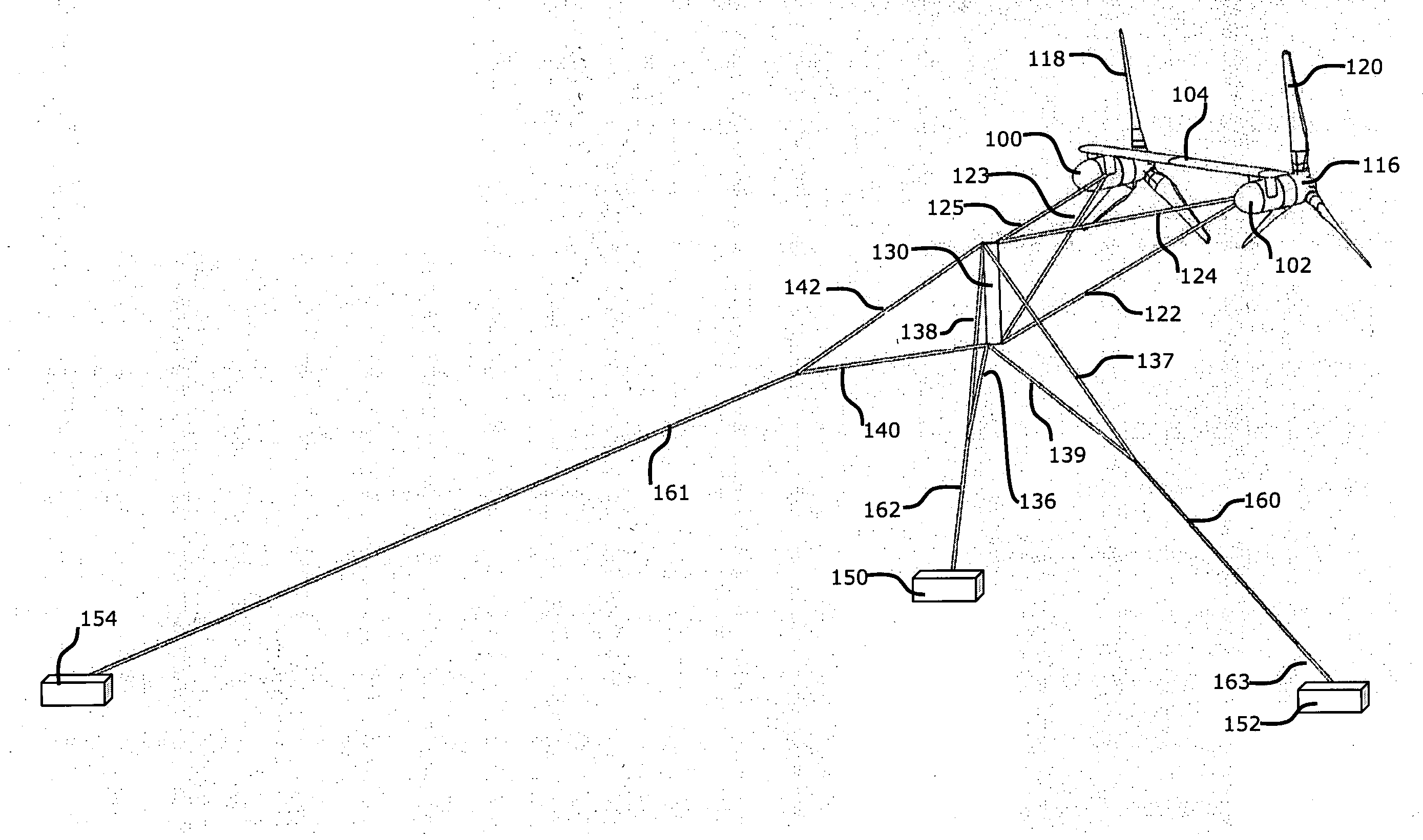
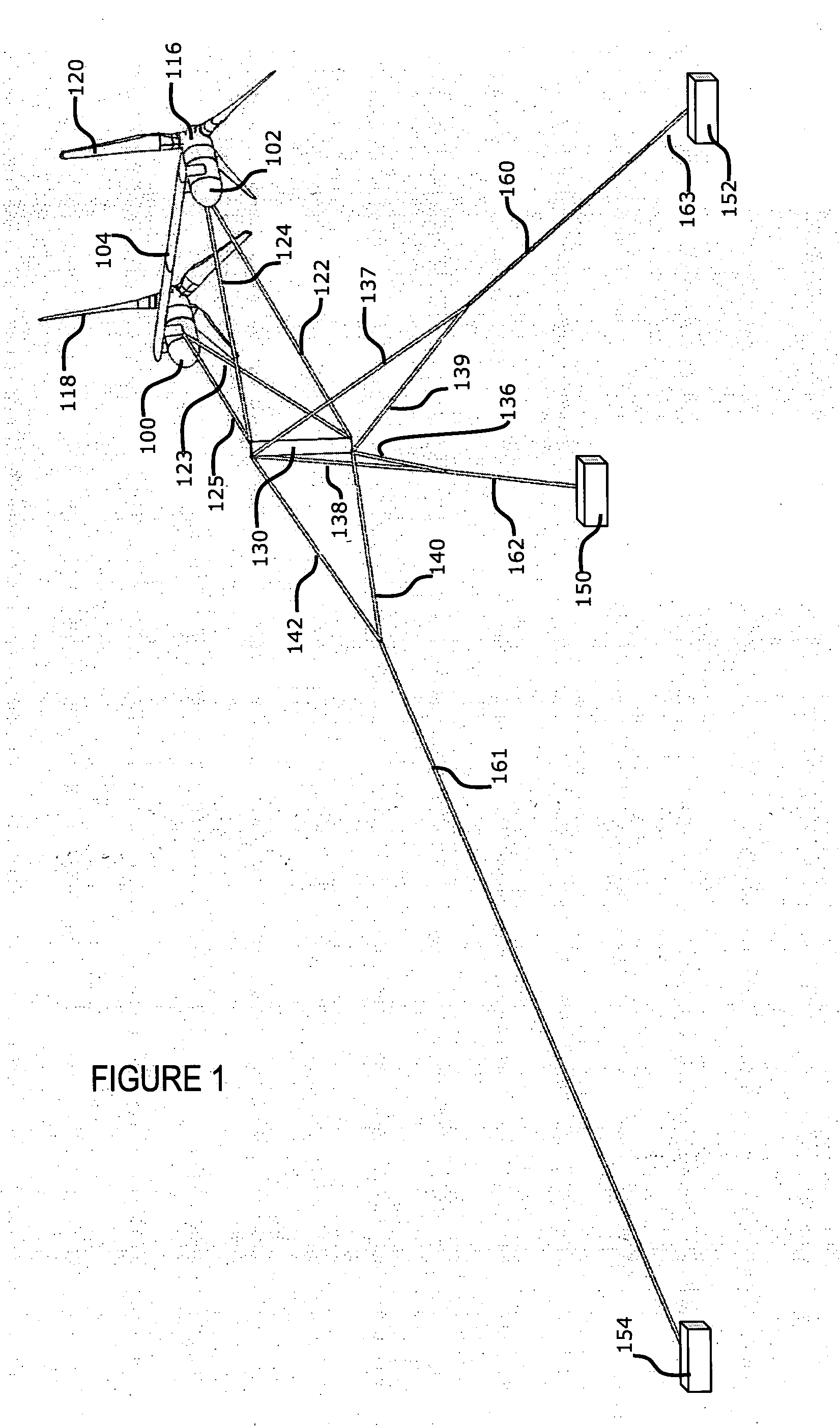
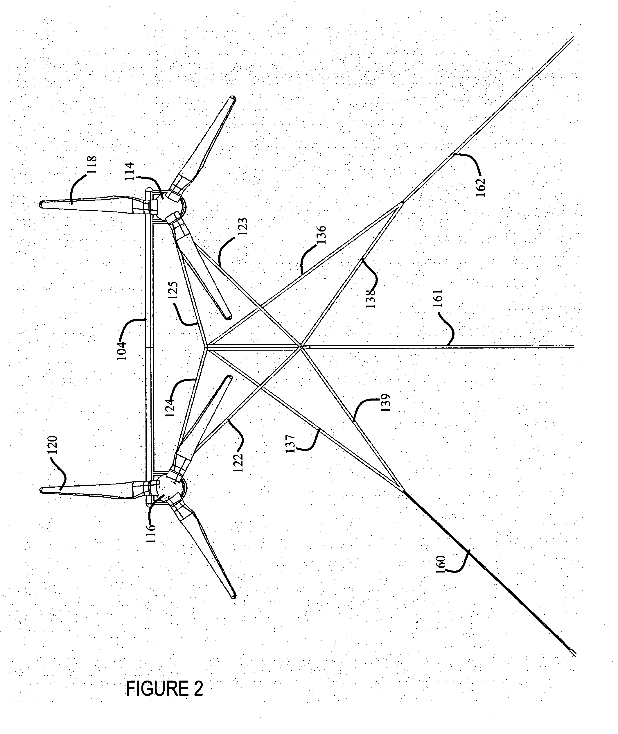
[0051]The invention relates to a multi-point tethering and stability system for underwater current turbines providing for yaw and depth adjustment capability in the current flow to optimize power extraction while maintaining operating stability in all degrees of freedom without requiring active lift or buoyancy adjustment and controls.

[0052]A method is described of tethering an underwater, water current-driven turbine, power-generating device to achieve stability in all degrees of freedom without the need to use buoyancy variation or lift adjusting mechanisms for depth adjustment that allows for yaw and depth adjustment in the current flow to optimize power extraction. The turbine includes variable-pitch rotor blades. A maximum allowable drag force load on the turbine rotors is selected. The pitch of the variable-pitch rotor blades on the turbine is adjusted such that the drag force loading of the device does not exceed a maximum design level.

[0053]The extraction of power in the for...


PUM


Abstract

A method of controlling a tethered, underwater, water current-driven turbine, power-generating device. The device is comprised of dual turbines and dual rotor blades turned by fluid flow, each turbine including one or more generators driven by rotor blades. The device is connected by device tethers to a strut, which is moveable to control depth of the device. The strut is connected to the ocean floor by tripodal tethers: a main tether, a left side tether and a right side tether, which are strut control tethers. One or more winches are controlled to maintain operation of the device within set parameters by varying the tension on one or more of the strut control tethers.

Description

BACKGROUND OF THE INVENTION[0001]1. Field of the Invention[0002]This invention relates to hydroelectric power-generating devices that use underwater currents to drive electricity-generating turbines.[0003]2. Description of the Prior Art[0004]The use of underwater power generators for generating electricity from water current flow, such as rivers and oceans, is known in the art. There are two types of prior devices: stationary turbines and tethered turbines. Stationary types of turbines are comprised of stationary towers based on the ocean floor. Electricity generating turbines are mounted on the towers at a fixed depth, with turbine rotor blades facing the flow of an ocean current. The disadvantages of this type of design are the underwater construction costs and the engineering challenges of deploying towers in deeper waters. Examples of these devices are being tested in Europe as tidal turbines and a few are being tested now in North American waters as of 2007.[0005]Tethered devic...

Claims


Application Information

Patent Timeline
Patent Type & Authority Applications(United States)
IPC IPC(8): F03B13/10
CPCB63B21/50B63B22/18B63B2035/4466F03B13/264F03B15/00Y02E10/28F05B2240/915F05B2240/917F05B2240/97F05B2250/21F05B2260/70F03B17/061F05B2240/9176Y02E10/30Y02E10/20
Inventor DEHLSEN, JAMES G.P.BROWN, MATTHEWGRIECO, CHRISTOPERH
Owner AQUANTIS
Learn More