Contactless power transmission apparatus and a method of manufacturing a secondary side thereof

a technology of contactless power transmission and secondary side, which is applied in the direction of transformer/inductance magnetic core, inductance, circuit arrangement, etc., can solve the problems of reducing the power in the secondary side, reducing the efficiency of transmission, and forming thin magnetic layers, so as to improve transmission efficiency and noise reduction. , the effect of further reducing the nois

Inactive Publication Date: 2010-07-22
PANASONIC CORP
View PDF19 Cites 96 Cited by
  • Summary
  • Abstract
  • Description
  • Claims
  • Application Information

AI Technical Summary

Benefits of technology

[0006]It is an object of the present invention to enhance the power transmission efficiency between primary and secondary sides and also to reduce the influence of noise from a planar coil. It is another object of the present invention to reduce the influence of heat and noise from the planar coil.
[0007]In a first aspect of the present invention, contactless power transmission apparatus comprises a secondary coil located in a secondary side, and is configured to transmit electric power from a primary side to the secondary side by electromagnetic induction between a primary coil and the secondary coil (hereinafter referred to as a “first configuration”). The primary coil is located in the primary side. The secondary side further comprises: a holding member which is physically separated from the primary side; a magnetic layer; a shield layer for shielding electromagnetic noise; and a heat insulation layer. The secondary coil is a planar coil and supported by the holding member. At least the magnetic layer is laminated on one side of the planar coil and unified with the planar coil. In the structure, since the magnetic layer is laminated to the planar coil, the power transmission efficiency between the primary and secondary sides can be enhanced. Since the secondary side includes the shield layer, the influence of noise from the planar coil can be reduced. Since the secondary side includes the heat insulation layer, the influence of heat and noise from the planar coil can be reduced.

Problems solved by technology

However, the planar coil is inferior in magnetic properties to the coil wound around a core, and accordingly power in the secondary side is reduced.
If a magnetic layer is added to the planar coil, the power transmission efficiency between the primary and secondary sides can be enhanced, but a thin magnetic layer must be formed, which becomes a problem.

Method used


Image

  • Contactless power transmission apparatus and a method of manufacturing a secondary side thereof
  • Contactless power transmission apparatus and a method of manufacturing a secondary side thereof
  • Contactless power transmission apparatus and a method of manufacturing a secondary side thereof

Examples


first embodiment

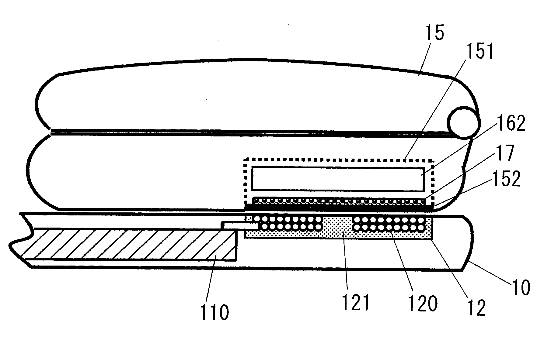
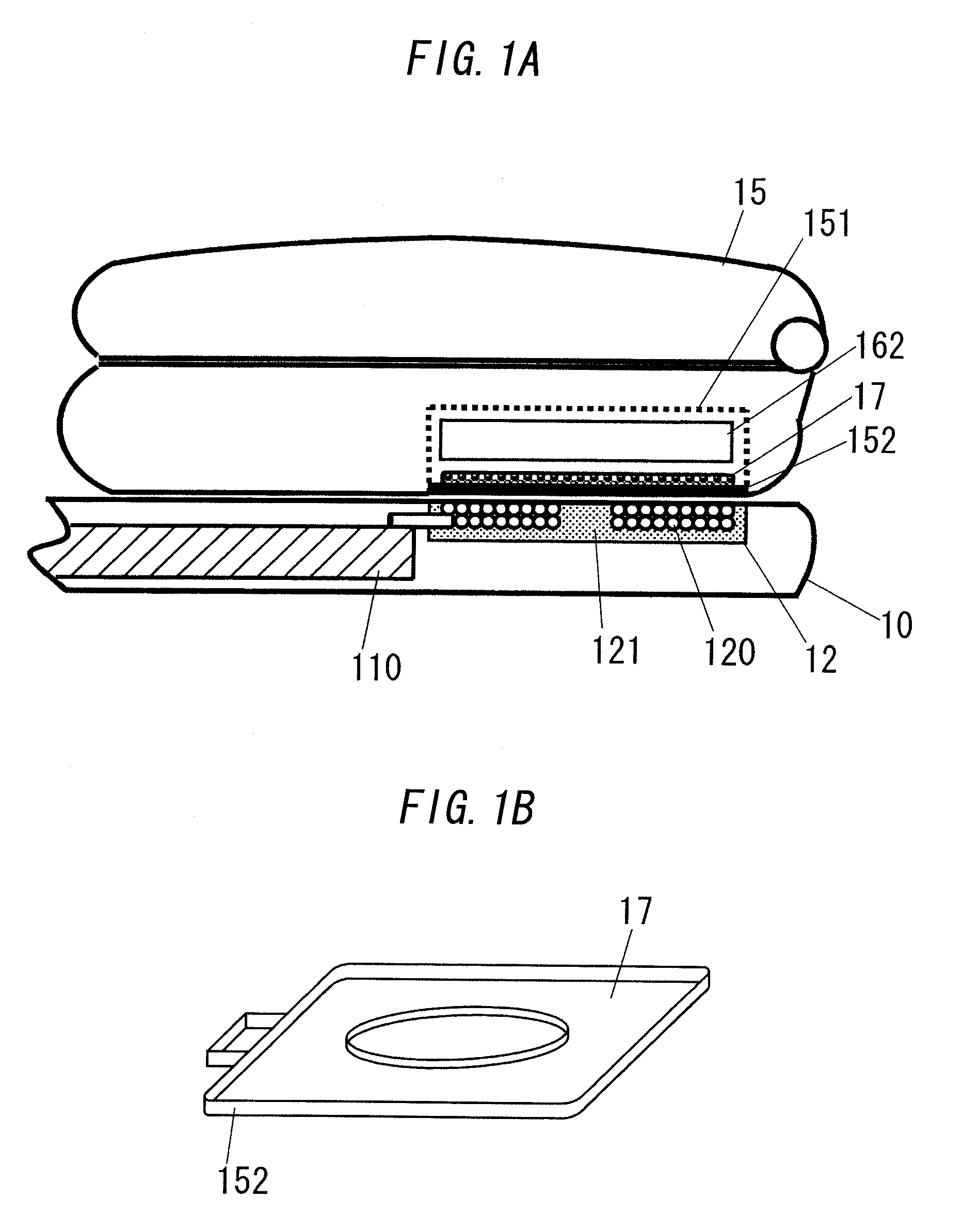
[0045]FIGS. 1A, 1B and 2 show contactless power transmission apparatus 1 in accordance with a first embodiment of the present invention. The apparatus 1 is broadly divided into a power transmitter 11 in a primary side and a power receiver 16 in a secondary side. The transmitter 11 and the receiver 16 include primary and secondary coils 120 and 170 capable of electromagnetic coupling, respectively, and are configured to transmit electric power from the primary side to the secondary side by electromagnetic induction between the primary and secondary coils 120 and 170. Accordingly, the transmitter 11 and the receiver 16 can be separated from each other. The transmitter 11 and the receiver 16 are, but not limited to, a charger 10 (a primary device) and a cell phone 15 (secondary device), respectively.

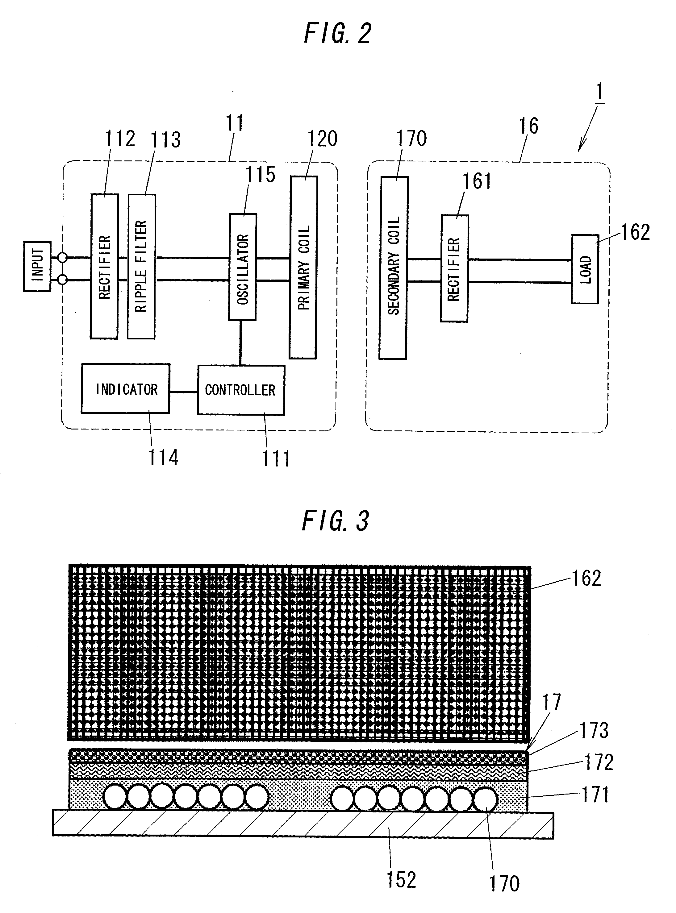
[0046]As shown in FIG. 2, the power transmitter 11 further includes a controller 111, a rectifier 112, a ripple filter 113, an indicator 114 and an oscillator 115, while the power receiver ...

second embodiment

[0064]FIG. 9 shows a power receiver in contactless power transmission apparatus in accordance with a second embodiment of the present invention. For the purpose of clarity, like kind elements are assigned the same reference numerals as depicted in the first embodiment.

[0065]The power receiver in the second embodiment further includes a radiation layer 174 intervened between the battery cover 152 and the secondary coil 170 in order to improve radiation characteristics from the battery cover 152. The radiation layer 174 can be made of the material that has high thermal conductivity and does not disturb magnetic flux coupling between the primary and secondary coils 120 and 170 (e.g., sheet shaped silicon)

third embodiment

[0066]FIG. 10 shows contactless power transmission apparatus in accordance with a third embodiment of the present invention. For the purpose of clarity, like kind elements are assigned the same reference numerals as depicted in the first embodiment.

[0067]In the third embodiment, a secondary coil block 17 and a functional member (a holding member) of a cell phone 15 are united. For example, as shown in FIGS. 10 and 11, the functional member is a load 162 (a secondary battery (a battery pack)), and the top of the secondary coil block 17, namely the upper surface of a heat insulation layer 173 is stuck on the bottom of the secondary battery with adhesive or pressure sensitive adhesive. However, not limited to this, the secondary coil block 17 and the secondary battery may be laminated with a wrapping film, or formed in a lump.


PUM

PropertyMeasurementUnit
switching frequencyaaaaaaaaaa
thicknessaaaaaaaaaa
diameteraaaaaaaaaa

Abstract

According to a first aspect, a secondary side of contactless power transmission apparatus includes: a holding member which is physically separated from a primary side; a magnetic layer; a shield layer for shielding electromagnetic noise; and a heat insulation layer. The secondary coil is a planar coil and supported by the holding member, and at least the magnetic layer is laminated on one side of the planar coil and unified with the planar coil. According to a second aspect, the secondary side of the apparatus includes a plurality of magnetic layers. Each permeability of the magnetic layers is different from each other, and each of the magnetic layers forms a magnetic path with the primary side.

Description

TECHNICAL FIELD[0001]The invention relates to contactless power transmission apparatus capable of transmitting electric power without any direct electric connection, and a method of manufacturing a secondary side of the apparatus.BACKGROUND ART[0002]That kind of contactless power transmission apparatus is broadly divided into a power transmitter in a primary side and a power receiver in a secondary side. The power transmitter includes a primary coil and is used for a device such as a charger or the like (hereinafter referred to as a “primary device”). The power receiver includes a secondary coil and is used for a device such as a cordless phone, a shaver, an electric toothbrush, a personal digital assistance or the like (hereinafter referred to as a “secondary device”). The primary and secondary coils constitute a transformer, and electric power is transmitted from the primary side to the secondary side by electromagnetic induction between the coils. Thus, the contactless power tran...

Claims


Application Information

Patent Timeline
Patent Type & Authority Applications(United States)
IPC IPC(8): H02J17/00H01B19/02H01F38/14
CPCH01F27/323Y10T29/49002H02J5/005H01F38/14H02J7/0042H02J50/80H02J50/70H02J50/10H02J50/12
Inventor SUZUKI, MASAYUKIKITAMURA, HIROYASUINAKAGATA, SATORUISAKA, ATSUSHIKEISHU, TATSUHIKO
Owner PANASONIC CORP
Why Eureka
Try Eureka