

F-69530 Brignais
- Summary
- Abstract
- Description
- Claims
- Application Information
AI Technical Summary
Benefits of technology
Problems solved by technology
Method used
Image

Examples
first embodiment
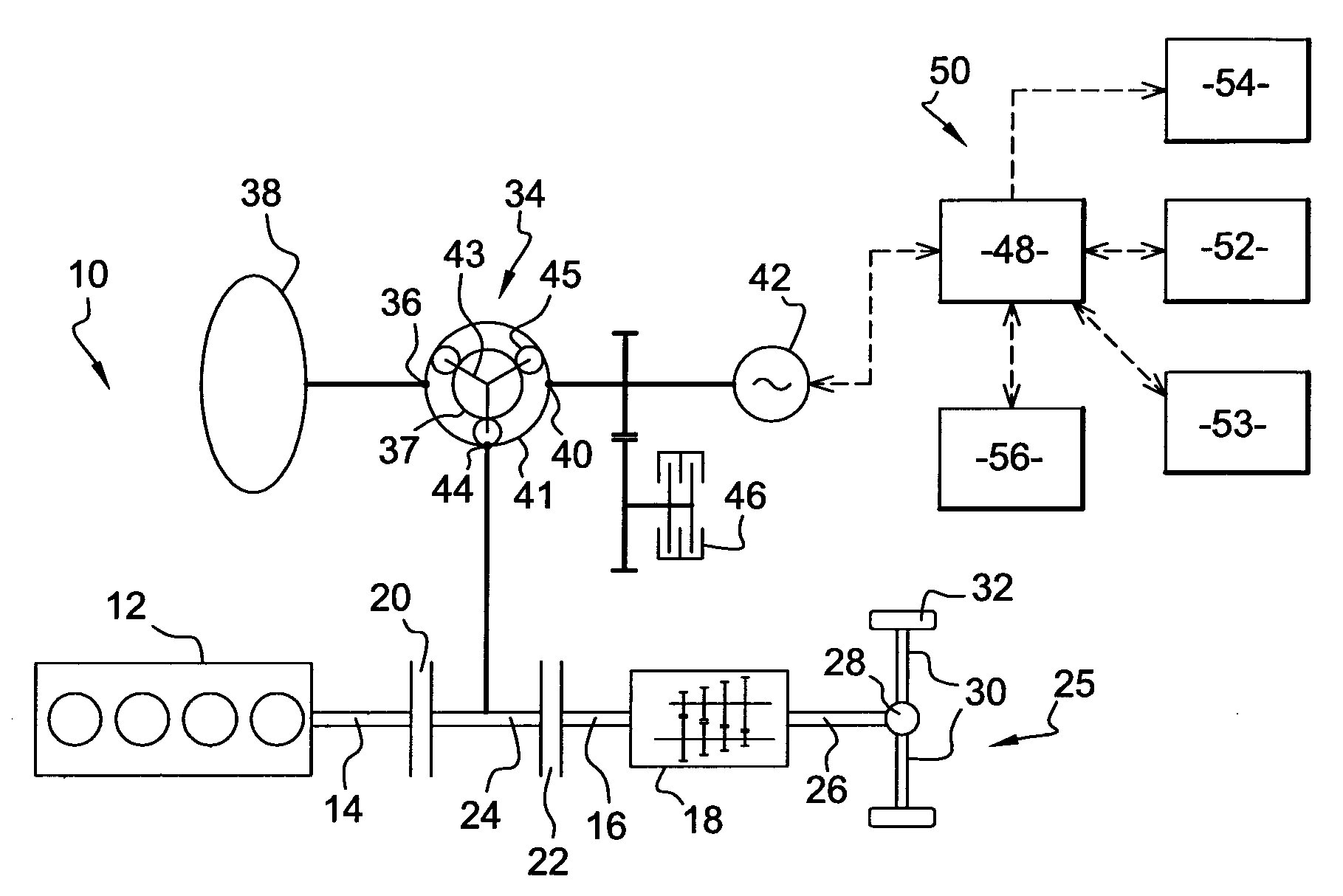
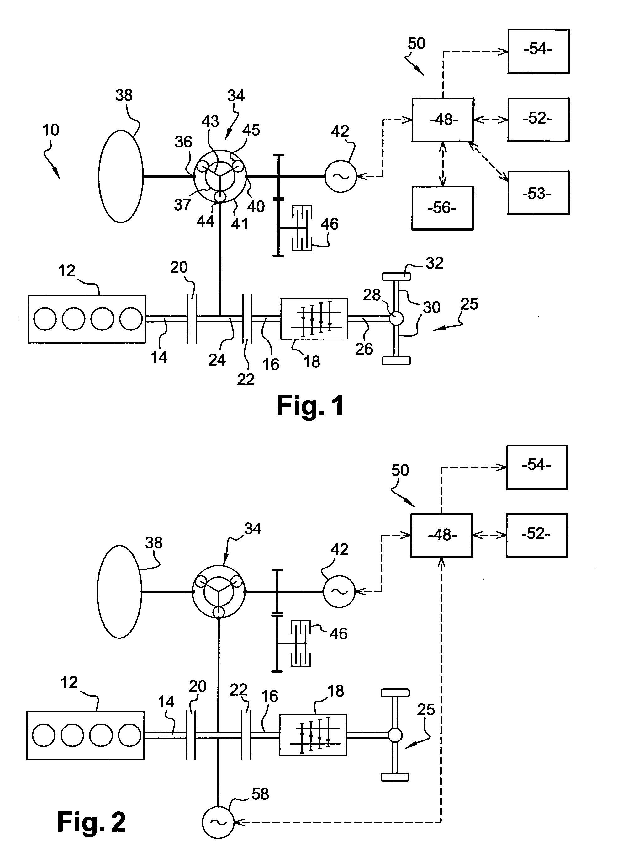
[0054]In this first embodiment of the invention shown on FIG. 1, the powertrain 10 has no active loads. As will be seen, all the energy which is used to run the first 42 electric machine comes from the electrical storage 52. The powertrain 10 must thus be tuned in order to reduce the rating of the electrical storage (in terms of capacity and of charging / discharging power) through a proper choice of the characteristics of the transmission and of the planetary gear 34.
[0055]The powertrain 10 according to the invention has different operating modes, some of which are described below, with reference to FIGS. 10 to 14b
[0056]FIGS. 10, 11a, 12a, 13a, 14a are based on the conventional speed diagram of a planetary gear. In the example shown, it is recalled that the sun wheel 37 is coupled to the flywheel 38, the ring wheel 41 is coupled to the first electrical machine 42 and the carrier 43 is coupled to the engine 12. On such a speed diagram the three vertical axis S, C, R represent respect...
second embodiment
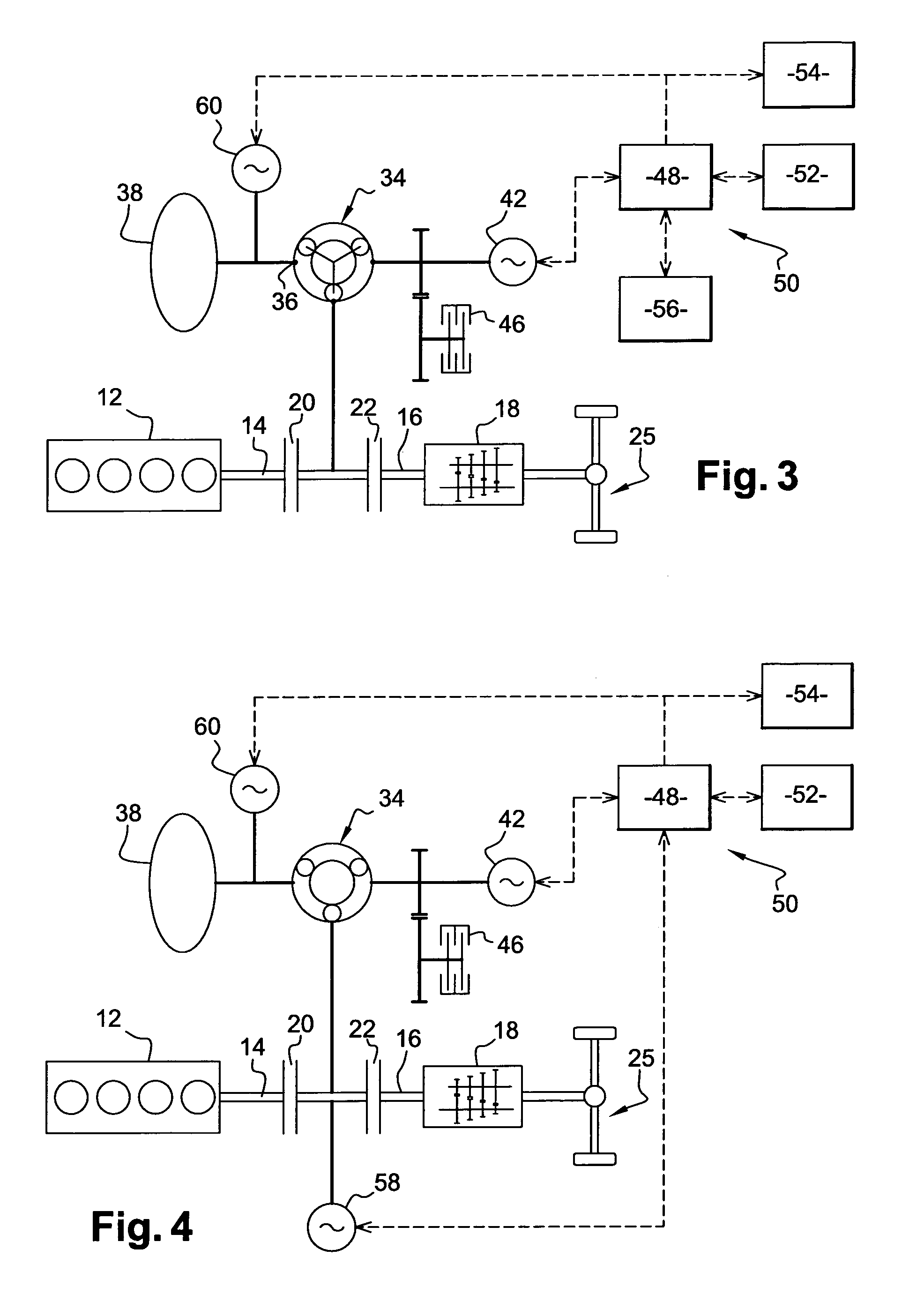
[0069]As in the second embodiment, the third electric machine 60 can be used to transfer energy from one storage means to the other, in order to manage their state of charge independently.
[0070]The third electric machine 60 can also assist the batteries to operate the first electrical machine by using an amount of energy from the flywheel 38. At last, the third electric machine 60 can be rated in order to provide most of the energy to operate the first electrical machine 42, so that the size of the batteries can be minimized.
[0071]The fourth embodiment shown on FIG. 4 is simply a combination of the second and third embodiments, with both the second 58 and the third 60 electrical machines as described above. This embodiment has the advantage of allowing an optimum and flexible management of the energy recovery, optimizing the use and storage of the energy. This embodiment enables to transfer part of the energy in electric mode to and from the flywheel.
[0072]In all the cases above, it...
PUM
 Abstract
Description
Claims
Application Information