Delivery apparatus for a retractable self expanding neurovascular stent

a delivery apparatus and self-expansion technology, applied in the field of neurovascular stent delivery apparatus, can solve the problems of inability to get the blood (and oxygen) the brain needs, affecting the safety of balloon-expansion stents, and affecting the safety of stents. the effect of tracking

Inactive Publication Date: 2010-07-22
ACHIEVA MEDICAL SHANGHAI
View PDF12 Cites 64 Cited by
  • Summary
  • Abstract
  • Description
  • Claims
  • Application Information

AI Technical Summary

Benefits of technology

[0012]The material composition and construction of the outer catheter changes over the length of it to create three distinct stiffness regions: proximal, middle, and distal. The inner shaft has also three distinct sections along the length of it. The variation of the stiffness from proximal end to distal end is to achieve better trackability inside the tortuous neurovascular path. As mentioned, the inner shaft includes at least one blocking member, to prevent any relative movement between the inner shaft and stent during advancement to the target neurovascular site, and also to allow retractable delivery of the stent to the target site, wherein physicians “pull” the stent back into the delivery apparatus if the placement is not optimal. Preferably, the inner shaft has reduced diameter inner member at the distal region, so as to be extending through the contracted stent interior, to enable stent and the inner shaft to be as an integral part during movement within the outer catheter.

Problems solved by technology

When that happens, part of the brain cannot get the blood (and oxygen) it needs, so it starts to die.
Safety of balloon-expandable stenting is often compromised by limited flexibility of the balloon-mounted stent delivery systems, high inflation pressure required to deploy stent in fragile intracranial vessels, the risk of shearing the stent off the balloon while navigating to the target lesion, and by difficulty in accurately sizing the stent to the vessel diameter.
Although a variety of intravascular self-expanding stents have been proposed heretofore, for example, in U.S. Pat. No. 4,665,906 issued to Jervis and U.S. Pat. No. 4,925,445 to Sakamoto et al, designing delivery systems for delivering self-expanding stent has proven difficult.
However, delivering the stent through the entire length of the catheter may cause many problems, including possible damage to a vessel or the stent during its travel.
The small and tortuous neurovascular pathway makes this system even more problematic because the pathway increases the risk of damage to the vessels and / or stent.
But, frequently these preloaded stents are misdeployed, meaning that the stent is not at the optimal position at the target site, because of either less that optimal placement of the outer catheter to the target site and / or because of movement of the apparatus during the deployment.
Some of the technical difficulties of the known delivery apparatus are misdeployment of the self-expanding stent if it was either too distal or too proximal to the target lesion.
However, the Escamilla devices do not work well for neurovascular arteries because the elongated core is solid, the guide wire normally needed for interventional procedure can not be inserted through the device, so the elongated core wire must function as guide wire as well.
It has proven difficult to design a core wire member having enough flexibility to navigate through tortuous neurovascular vessels as the guiding wire, but also enough stiffness to push the stent out of the catheter or pull the stent back into the catheter.
Furthermore, the stent, in a constrained state, being mounted on the intermediate cylindrical member, may be damaged or deformed by the intermediate cylindrical member during advancement to the target disease site or during stent deployment.
For such small size scale, it is not easy to fabricate the devices, neither assemble the devices together.
Moreover, cutting such grooves into the inner shaft of a small neurovascular delivery apparatus will result in a delivery apparatus that is too weak for delivery through a tortuous pathway and that will be easily torn under the required stresses for delivery and retractable deployment of the stent.

Method used


Image

  • Delivery apparatus for a retractable self expanding neurovascular stent
  • Delivery apparatus for a retractable self expanding neurovascular stent
  • Delivery apparatus for a retractable self expanding neurovascular stent

Examples


Embodiment Construction

[0046]As is used herein, the terms “about” or “approximate” when used to describe the dimensions of the described device mean that the size of the device need not be precisely the dimensions described. Those of skill in the art will understand from this disclosure how to design embodiments of the invention with varied dimensions. Such is within the spirit of this current invention.

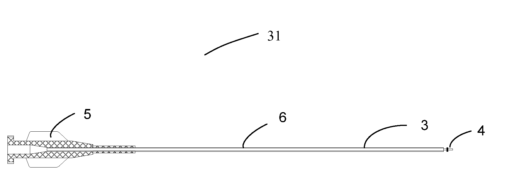
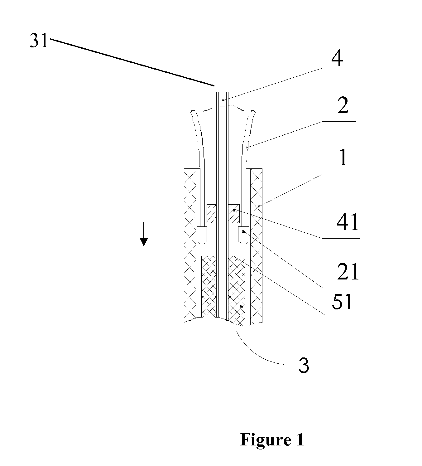
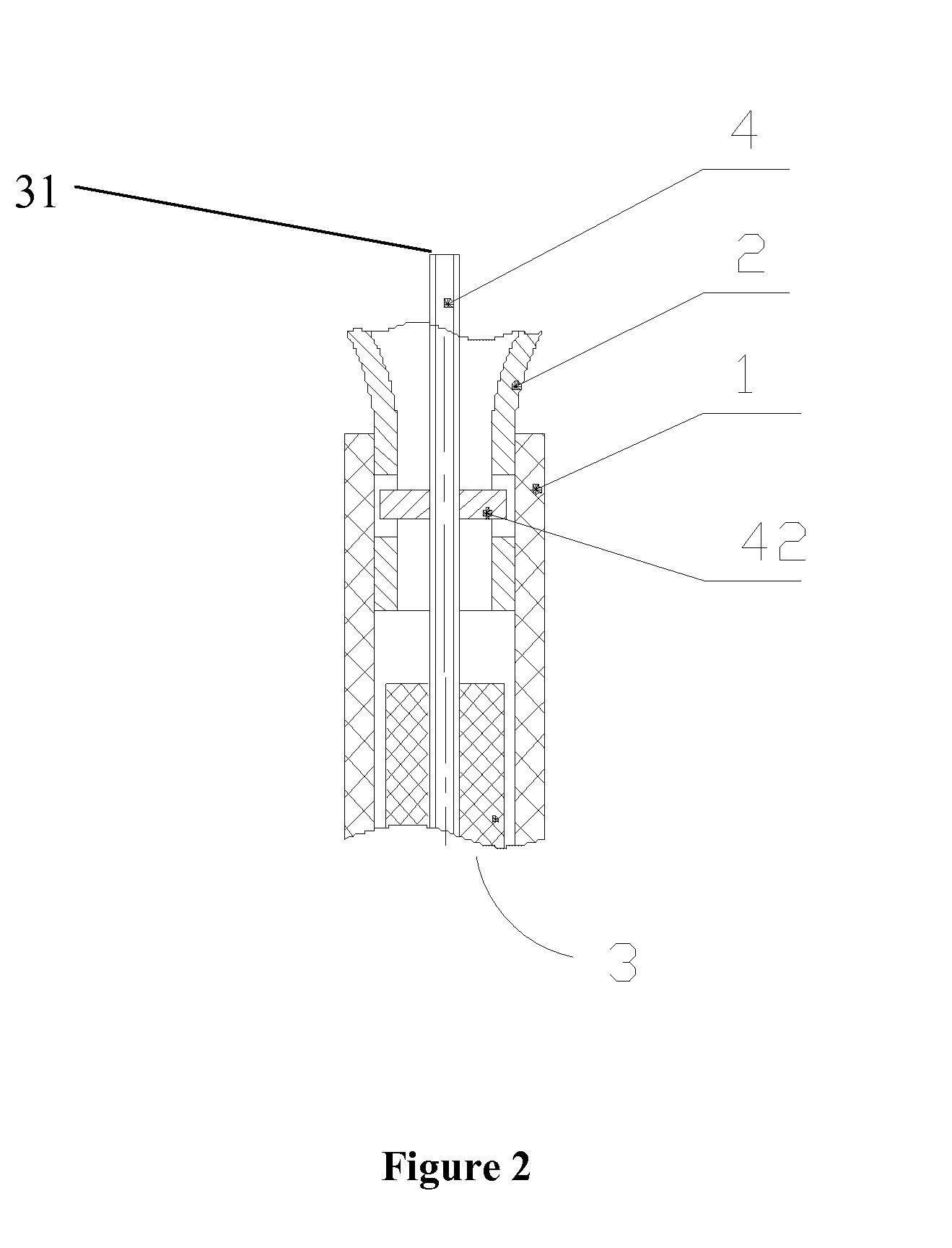
[0047]FIG. 1 and FIG. 2 illustrate two exemplary embodiments of a neurovascular self expanding stent delivery apparatus of the current invention. In FIG. 1 there is seen a distal section 4 and a middle section 3 of an inner shaft 31. Attached to the inner shaft 31 there is a first blocking member 41. FIG. 3 is partial exploded views of the distal end of the inner shaft 31, wherein the blocking member 41 is a disc-shape disposed on the inner shaft. Returning to FIG. 1, the larger outer diameter of the middle section 3 of inner shaft 31 compared to the outer diameter of the distal section 4 provides a second...


PUM


Abstract

The present invention relates to a delivery apparatus for delivering a self-expanding neurovascular stent that allows for smooth movement of the apparatus along a typically tortuous vascular path, ease of stent deployment, and ease of stent retractability being pushed and pulled through the delivery apparatus. The apparatus includes an outer catheter, and an inner shaft located coaxially within the outer catheter. The stent is mounted on the distal section of the inner shaft and preloaded within the outer catheter distal region. The inner shaft includes at least one stent blocking member disposed in the distal section. The self-expanding stent has proximal, middle and distal ends and is comprised of a plurality of closed cells. The self-expanding stent includes locking members which interlock with the blocking member(s) disposed on the inner shaft so as to lock the stent onto the inner shaft within the outer catheter, and to enable the stent retractable together with the inner shaft being out of and retrieved back to the outer catheter. More specially, the invention may be used in the treatment of blood vessel blockage and aneurysms which occur in the brain.

Description

PRIORITY DOCUMENTS[0001]This Application claims the benefit of Chinese patent application number 200910045521.8, filed Jan. 19, 2009, which is incorporated herein by reference.FIELD OF THE INVENTION[0002]The present invention relates to a neurovascular stent delivery apparatus for delivering a self-expanding neurovascular stent to a neurovascular target site, that allows for smooth movement of the apparatus along a typically tortuous vascular path, ease of stent deployment, and ease of stent retractability being pushed and pulled through the delivery apparatus.BACKGROUND OF THE INVENTION[0003]It is well documented that annually in the United States, approximately 780,000 patients will experience new or recurring stroke. Stroke affects the arteries leading to and within the brain. A stroke occurs when a blood vessel that carries oxygen and nutrients to the brain is either blocked by intracranial atherosclerotic clot (ischemic stroke) or bursts (hemorrhagic stroke). When that happens,...

Claims


Application Information

Patent Timeline
Patent Type & Authority Applications(United States)
IPC IPC(8): A61F2/84A61F2/966A61M29/00
CPCA61F2/07A61F2/915A61F2/95A61F2/966A61F2002/91525A61F2002/91558A61F2002/9505A61F2002/9665A61F2250/0018A61F2250/0098A61F2230/0054
Inventor ZHANG, YI
Owner ACHIEVA MEDICAL SHANGHAI
Why Eureka
Try Eureka