Micromechanical rotation rate sensor with a coupling bar and suspension spring elements for quadrature suppression

a micromechanical and rotational speed sensor technology, applied in the direction of acceleration measurement using interia forces, turn-sensitive devices, instruments, etc., can solve the problems of unfavorable measurement, sensitive interference excitation of the seismic mass coupling by means of the proposed coupling unit, and undetectable edge angles of the respective structur

Active Publication Date: 2010-07-29
CONTINENTAL TEVES AG & CO OHG
View PDF14 Cites 64 Cited by
  • Summary
  • Abstract
  • Description
  • Claims
  • Application Information

AI Technical Summary

Benefits of technology

[0008]An object of the present invention is to propose a micromechanical rotation rate sensor which measures relatively precisely or

Problems solved by technology

The seismic masses are suspended directly from the substrate, wherein this suspension means is embodied in such a way that it has to ensure the deflection capability of the seismic masses both for the drive modes and for the reading modes of the rotation rate sensor, as a result of which undesired crosstalk between the two oscillation modes can occur, and this has an adverse effect on the measurement.
However, the coupling of the seismic masses by means of the proposed coupling unit is sensitive to interference excitations oriented in the same direction in the measuring direction, su

Method used


Image

  • Micromechanical rotation rate sensor with a coupling bar and suspension spring elements for quadrature suppression
  • Micromechanical rotation rate sensor with a coupling bar and suspension spring elements for quadrature suppression
  • Micromechanical rotation rate sensor with a coupling bar and suspension spring elements for quadrature suppression

Examples


Embodiment Construction

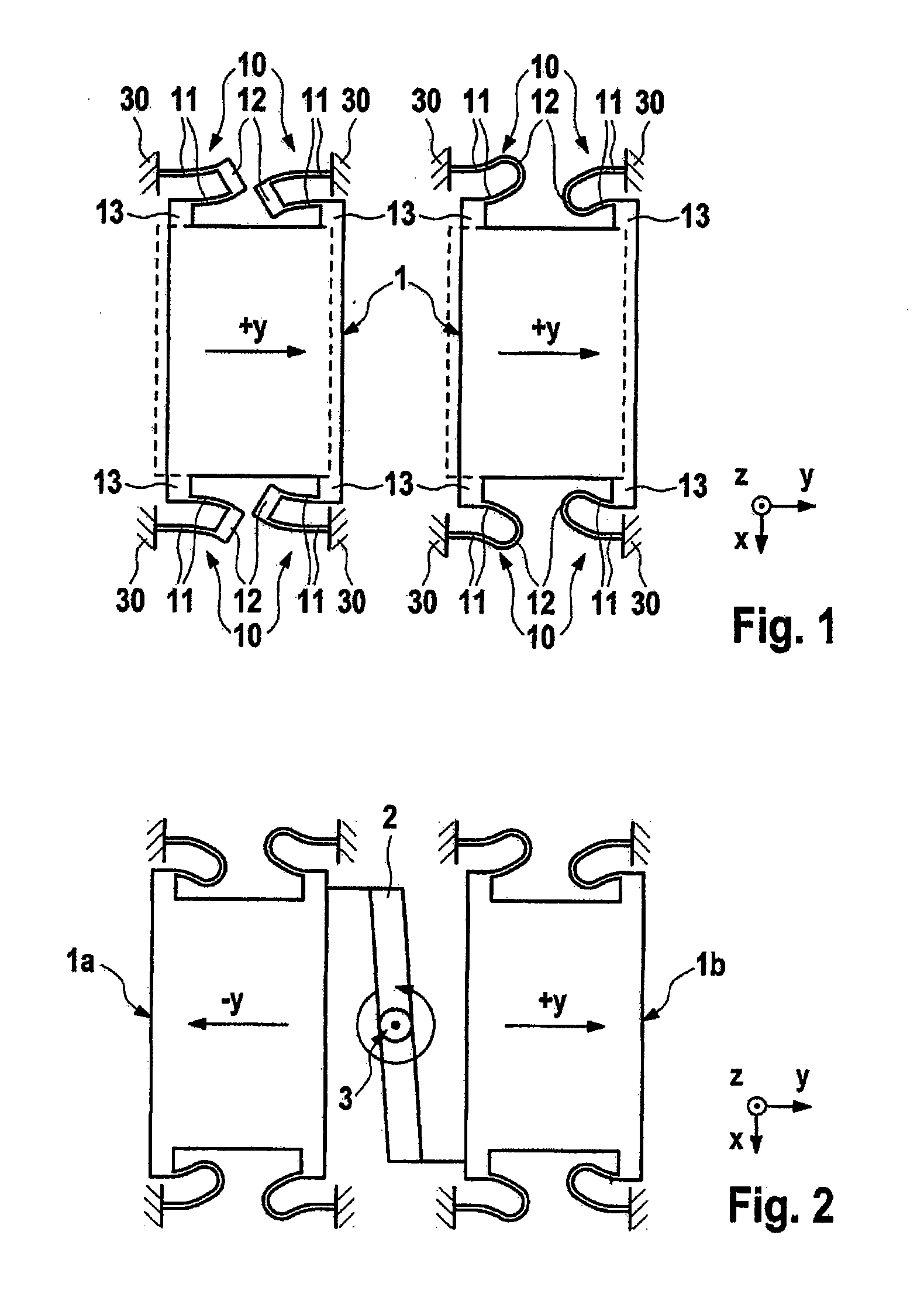
[0076]FIG. 1 shows two exemplary embodiments for suspending a seismic mass 1 from the substrate 30 by means of four exemplary proposed suspension spring elements or linear springs 10. The latter prevent quadrature signals occurring due to possible tilting of the spring cross sections as a result of fabrication inaccuracies. The two illustrated exemplary embodiments of the suspension spring elements or linear springs 10 each comprise here two bar sections 11, a connection section 12 and a coupling region 13, which connects one of the bar sections to the seismic mass 1. The oscillators illustrated in FIG. 1 are each deflected in the y direction, as is indicated by the dashed line. The suspension spring elements 10 are correspondingly likewise depicted deflected in the y direction.

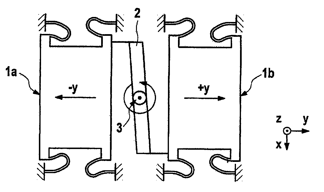
[0077]FIG. 2 illustrates the coupling of two seismic masses 1a, 1b by means of a coupling bar 2. The rotational suspension means 3 of the coupling bar permits rotation about the z axis, perpendicular to the p...


PUM


Abstract

A micromechanical rotation rate sensor including at least one substrate, wherein the base surface of the substrate is oriented parallel to the x-y plane of a Cartesian coordinate system, at least two seismic masses and in each case at least one suspension spring element for suspending the seismic mass from the substrate, wherein the at least two seismic masses are coupled to one another by at least one coupling bar, and at least one of the suspension spring elements includes at least two bar sections, which, in the undeflected state, are oriented essentially parallel to one another or are at an angle of less than 45° with respect to one another, and one or more connecting sections, which connect the bar sections to one another, wherein the bar sections can be displaced relative to one another in their longitudinal direction.

Description

CROSS REFERENCE TO RELATED APPLICATIONS[0001]This application is the U.S. national phase application of PCT International Application No. PCT / EP2008 / 060802, filed Aug. 18, 2008, which claims priority to German Patent Application No. 10 2007 042 681.1, filed Sep. 10, 2007, and German Patent Application No. 10 2007 057 042.4, filed Nov. 27, 2007, the contents of such applications being incorporated by reference herein.FIELD OF THE INVENTION[0002]The invention relates to a rotation speed sensor, to a method for manufacturing a rotation rate sensor and to the use of the rotation rate sensor in motor vehicles.BACKGROUND OF THE INVENTION[0003]Rotation rate sensors are usually used to sense the angular speed of a system about at least one defined axis. An important field of application of rotation rate sensors is motor vehicle engineering, for example in vehicle movement dynamics control systems such as the electronic stability program (ESP) or what is referred to as a rollover detection m...

Claims


Application Information

Patent Timeline
IPC IPC(8): G01P3/44H01L21/02G01C19/56
CPCG01C19/574
Inventor GUNTHNER, STEFANSCHMID, BERNHARD
Owner CONTINENTAL TEVES AG & CO OHG
Why Eureka
Try Eureka