Refrigerating apparatus

a technology of refrigerating apparatus and heat exchanger, which is applied in the direction of domestic cooling apparatus, lighting and heating apparatus, milk preservation, etc., can solve the problems of water flowing through the heat exchanger not being heated sufficiently, the refrigerant cannot absorb the heat from the cooling target, and the refrigerating cycle is brought into an overloaded state, etc., to achieve the effect of safe and secur

Active Publication Date: 2010-07-29
SANYO ELECTRIC CO LTD
View PDF7 Cites 24 Cited by
  • Summary
  • Abstract
  • Description
  • Claims
  • Application Information

AI Technical Summary

Benefits of technology

[0019]In consequence, while eliminating the disadvantage that the heat radiation amount of the refrigerant in the water heat exchanger r

Problems solved by technology

In this case, however, the water supplied from the hot water storage tank and flowing through the heat exchanger is the sufficiently heated high temperature hot water, whereby the heat taken from the cooling target by the refrigerant in the evaporator cannot be released from the heat exchanger, which causes a problem that the refrigerating cycle is brought into an overloaded state.
In this c

Method used


Image

  • Refrigerating apparatus
  • Refrigerating apparatus
  • Refrigerating apparatus

Examples


embodiment 1

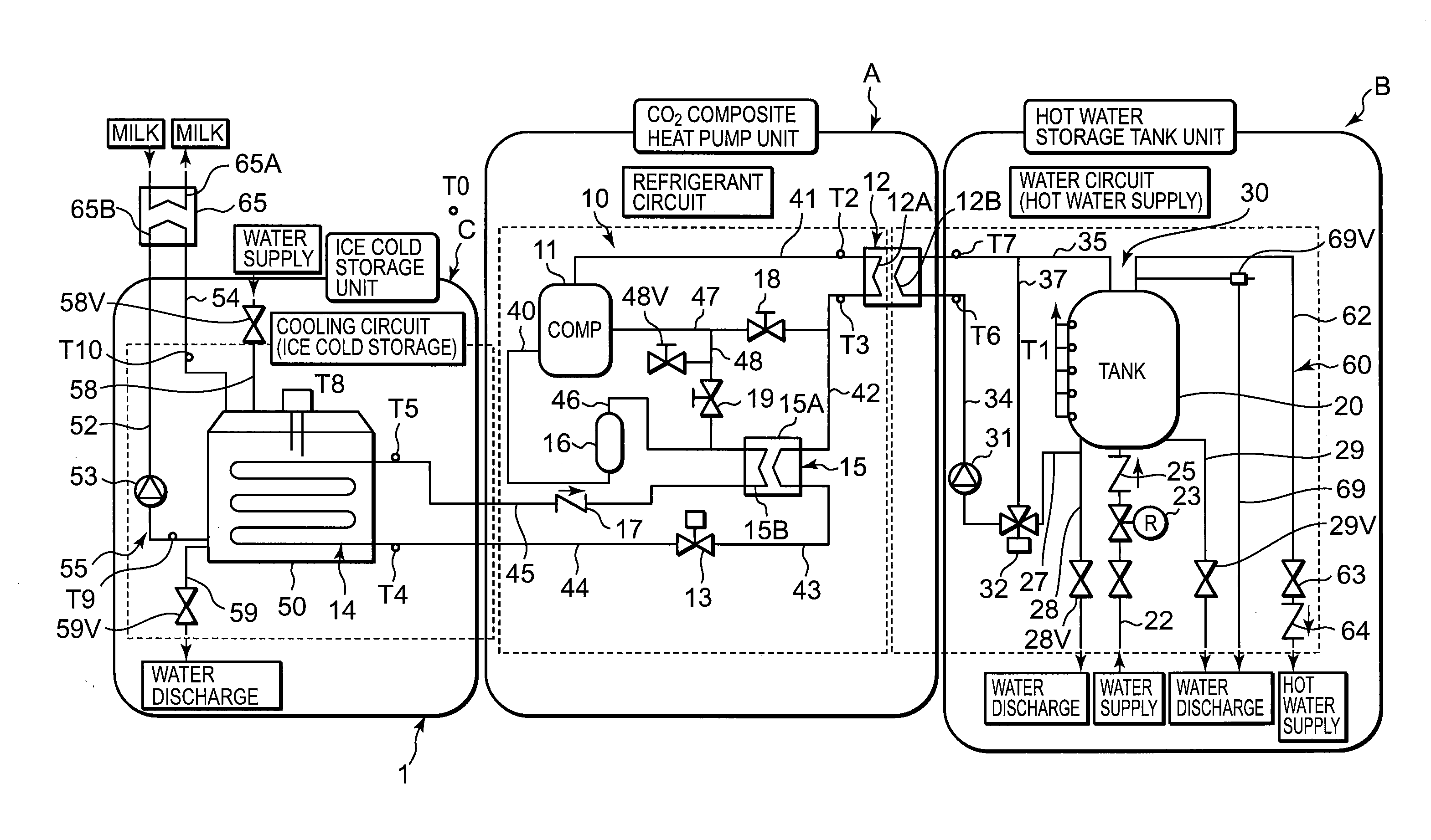
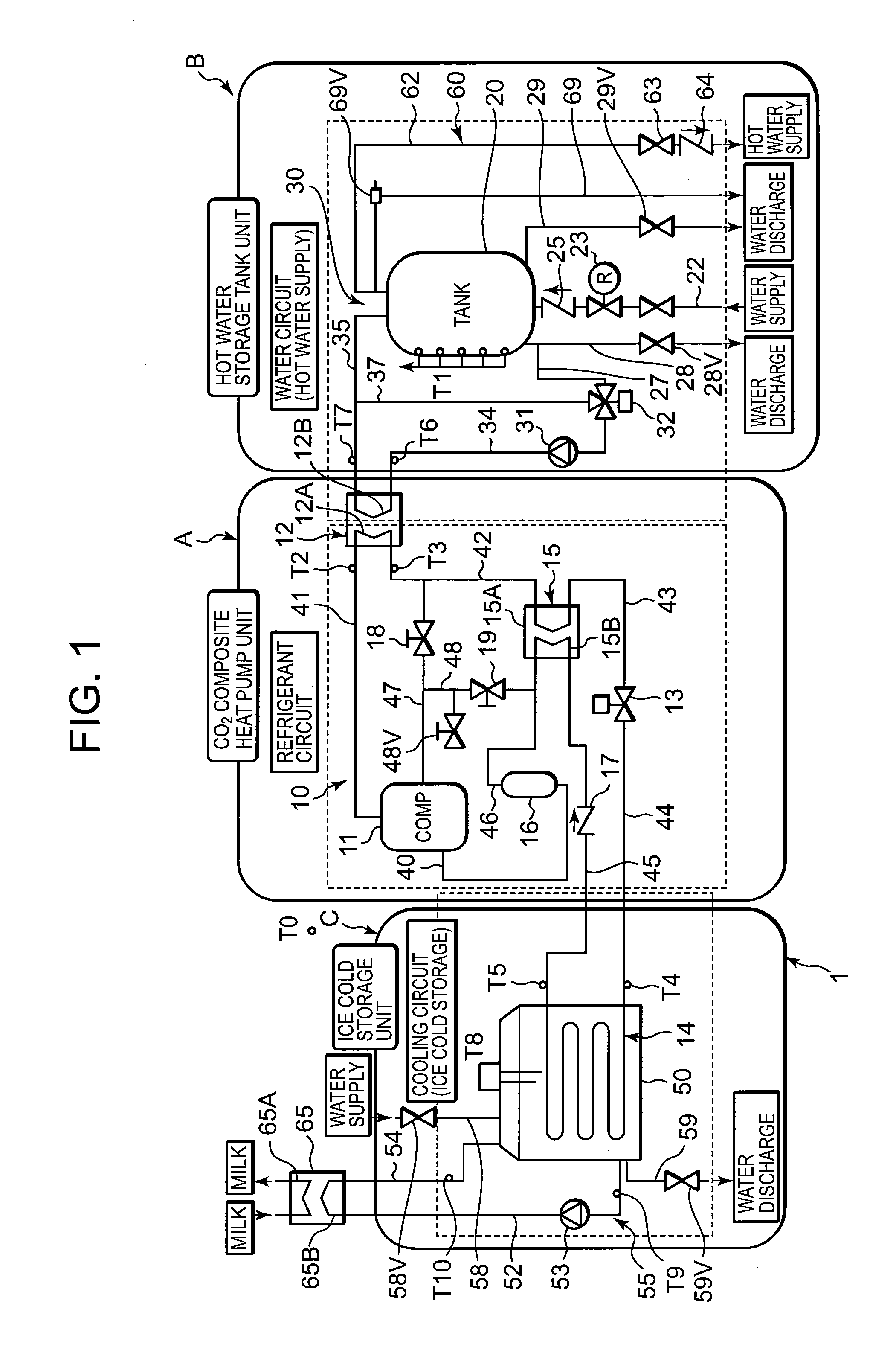
[0025]FIG. 1 shows a circuit diagram of a refrigerating apparatus 1 of one embodiment to which the present invention is applied. The refrigerating apparatus 1 of the present embodiment is constituted of a heat pump unit (a CO2 composite heat pump unit) A having a refrigerant circuit 10, a hot water storage tank unit B including a hot water storage tank 20, a water circuit 30 through which water is circulated between a water heat exchanger 12 of the refrigerant circuit 10 and the hot water storage tank 20, and an ice cold storage unit (a cold storage unit) C having an ice cold storage tank 50.

[0026]In the heat pump unit A, water (tap water supplied to the hot water tank) from the hot water storage tank 20 is heated to produce high-temperature water (hot water), and water in the ice cold storage tank 50 of the ice cold storage unit C is cooled to produce ices. In the heat pump unit A of the embodiment, a refrigerant compressor 11, a refrigerant passage (a radiator) 12A of the water he...

embodiment 2

[0102]It is to be noted that it has been described in the above embodiment that the control unit Z performs the operation start judgment control to judge the operation time by the timer as its function and to start the operation in the step S1 (FIG. 4) as described above, but the present invention is not limited to this embodiment, and the control unit may start the operation by the lowering of the cooling ability of the ice cold storage unit C. Specifically, in step S18 shown in FIG. 4, the control unit Z judges whether or not a circulation pump 53 (corresponding to a cold water pump of the step S18 of FIG. 4) is operated, and advances to step S19 when the pump is operated (YES), but returns to the step S18 when the pump is not operated (NO), and repeats the step S18 until the circulation pump 53 is operated.

[0103]Next, in the step S19, the control unit Z detects, by a temperature sensor T9, the temperature of cold water discharged from an ice cold storage tank 50 to a forwarding p...


PUM


Abstract

An object is to provide a refrigerating apparatus which eliminates a disadvantage that a refrigerant circuit is overloaded and which can safely be operated. The refrigerating apparatus includes a control unit which starts the operation of a refrigerant compressor of the refrigerant circuit in response to an operation signal and which regulates an expansion valve so that the temperature of a refrigerant in a water heat exchanger becomes +80° C. or more and so that the temperature of the refrigerant in an evaporator becomes 0° C. or less. The control unit detects a state of a case where a cold storage amount in an ice cold storage tank of an ice cold storage unit reaches a predetermined amount or more and a state of a case where the control unit judges that a hot water storage tank is full of hot water, after the elapse of a predetermined time from the start of the operation of the compressor, and stops the operation of the compressor when one of the states is satisfied.

Description

BACKGROUND OF THE INVENTION[0001]The present invention relates to a refrigerating apparatus including a refrigerant circuit in which a refrigerant compressor, a water heat exchanger, a pressure reducing device and an evaporator are annularly connected by piping, and the refrigerating apparatus is configured to heat water supplied from a hot water storage tank and circulated through a water circuit by the water heat exchanger and to cool ambient water by the evaporator, thereby enabling cold storage.[0002]Heretofore, as a method for cooling a cooling target such as food or beverage, a refrigerating apparatus using an evaporating compression type refrigerating cycle has broadly been utilized. In this type of refrigerating apparatus, the cooling target is cooled by a heat absorbing function by the evaporation of a refrigerant in an evaporator, and heat is radiated to the atmosphere by the heat radiation of the refrigerant in a radiator.[0003]In recent years, in this type of refrigerati...

Claims


Application Information

Patent Timeline
IPC IPC(8): A23C3/04F25B1/00F25D17/02F25C1/00
CPCF25B29/003F25B2309/061F25B2600/2513F25D31/002
Inventor OTAKE, MASAHISAHASEGAWA, SETSUKAWAKUBO, KENSASAKI, HIDETAKA
Owner SANYO ELECTRIC CO LTD
Why Eureka
Try Eureka