Component feeder

Active Publication Date: 2010-07-29
YAMAHA MOTOR CO LTD
View PDF4 Cites 9 Cited by
  • Summary
  • Abstract
  • Description
  • Claims
  • Application Information

AI Technical Summary

Benefits of technology

[0015]According to one aspect of the present invention, the first feeding device and the second feeding device which convey the component housing tape are provided, and the electronic component exposing device is provided between the first feeding device and the second feeding device, whereby conveyance of the component housing tape can be made stable, and therefore, a component feeder which can enhance conveyance precision of the component housing tape, can move the electronic components to the component extracting position with high precision, can accurately extract the electronic components, and can enhance productivity

Problems solved by technology

However, in JP-A-04-22196, the cover tape removing means is provided between the feeding reel and the pitch feeding means, and therefore, if the winding diameter of the component housing tape wound on the housing tape reel changes when the component housing tape is conveyed, the conveyance resisting force received from the housing tape reel changes, which causes the possibility of worsening the conveyance precision

Method used


Image

  • Component feeder
  • Component feeder
  • Component feeder

Examples


embodiment 1

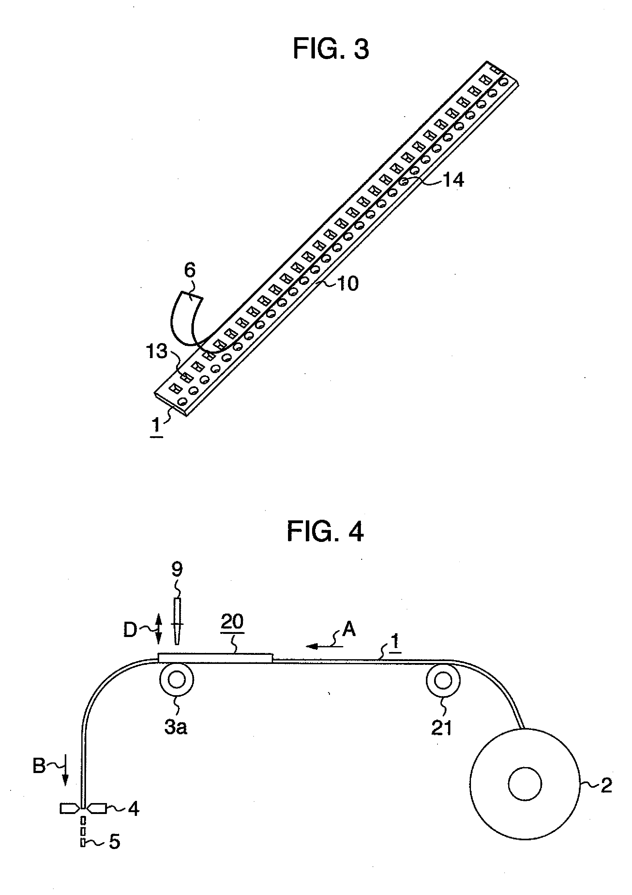
[0027]A schematic constitution of a component feeder of embodiment 1 of the present invention will be described with use of FIG. 4. As shown in FIG. 4, a component housing tape 1 which is wound on a housing tape reel 2 is taken in the component feeder through an inlet port for taking in a component housing tape provided in a casing of the component feeder not illustrated, and is conveyed in the direction of arrow A by a second feeding device 21 while being supported by a guide not illustrated. The housing tape reel 2 may be held by and fixed to the inlet port to be replaceable, or may be held at the position apart from the component feeder. The second feeding device 21 may be the one in a gear shape having a projecting portion engaged with holes provided in the component housing tape 1, or may be the one formed by having a pair of rollers which pinch on the top surface and the undersurface of the component housing tape. An electronic component exposing device 20 which is provided be...


PUM


Abstract

A component feeder capable of enhancing productivity is provided by that the component feeder includes a tape feeding device intermittently feeding a component housing tape constituted of a carrier tape having component housing parts formed with predetermined interval to contain respective electronic components, and a cover tape covering the component housing parts to prevent the components from jumping out from the component housing parts while the component housing tape wound on a housing tape reel is sequentially fed to a component extracting position, and an electronic component exposing device exposing the electronic components in the component housing parts to be allowed to be extracted, wherein the tape feeding device is constituted of a first feeding device and a second feeding device, and the electronic component exposing device is provided between the first feeding device and the second feeding device.

Description

BACKGROUND OF THE INVENTION[0001]The present invention relates to a component feeder. The present invention relates to, for example, a component feeder including a tape feeding device which sequentially feeds a component housing tape constituted of a carrier tape on which component housing parts for housing electronic components are formed by being arranged at predetermined spaces, and a cover tape provided to cover the component housing parts formed on the carrier tape for preventing the components from jumping out of the component housing parts, in the state in which the component housing tape is wound on a housing tape reel, and intermittently feeds the component housing tape to a component extracting position, and an electronic component exposing device which exposes electronic components in the component housing parts to allow the electronic components to be taken out.[0002]By using FIGS. 1 to 3, a component feeder as a comparative example of the present invention will be shown...

Claims


Application Information

Patent Timeline
IPC IPC(8): B32B37/00
CPCY10T225/22H05K13/0419Y10T156/12Y10T156/17H05K13/02H05K13/04
Inventor IKEDA, HIROSHIUSUI, YOSHINAOOYAMA, KAZUYOSHIYANAGIDA, TSUTOMUTAKAHIRA, ISAO
Owner YAMAHA MOTOR CO LTD
Why Eureka
Try Eureka