Drive Unit for a Hybrid Vehicle and Method of Assembly

Inactive Publication Date: 2010-07-29
ZF FRIEDRICHSHAFEN AG
View PDF6 Cites 5 Cited by
  • Summary
  • Abstract
  • Description
  • Claims
  • Application Information

AI Technical Summary

Benefits of technology

[0008]An object of the invention is to provide a compact and easy-to-assemble drive unit with an internal combustio

Problems solved by technology

For a motor vehicle manufacturer, this assemb

Method used


Image

  • Drive Unit for a Hybrid Vehicle and Method of Assembly
  • Drive Unit for a Hybrid Vehicle and Method of Assembly

Examples


Embodiment Construction

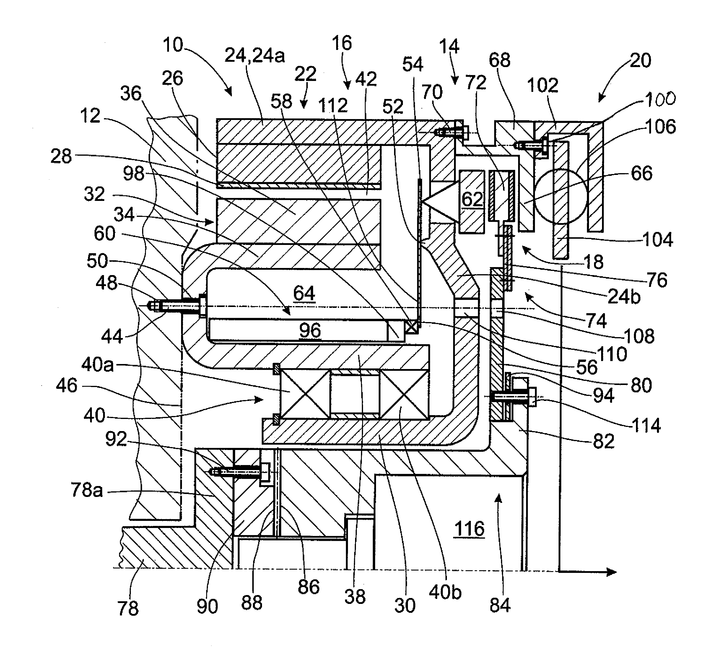
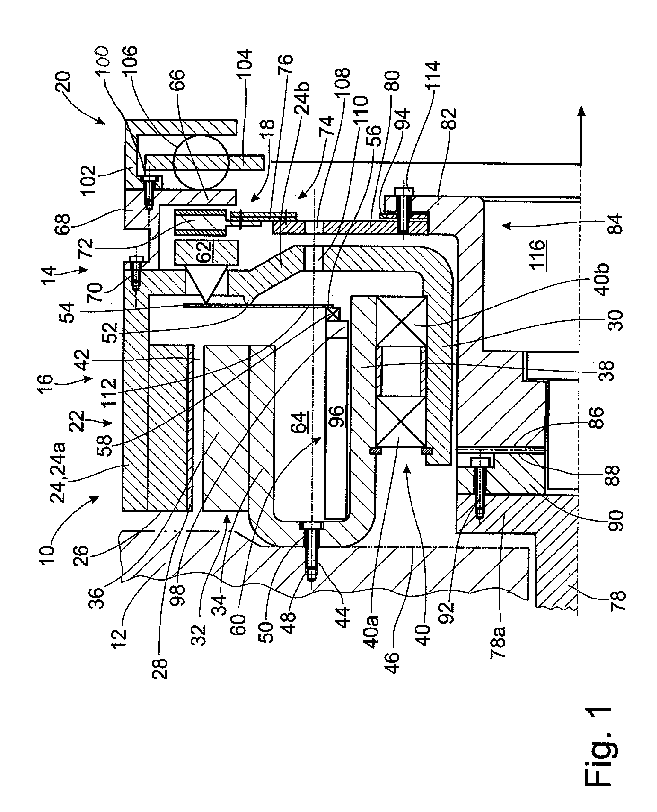
[0022]FIG. 1 schematically depicts an axial cross section through a drive unit 10 for a hybrid vehicle consisting of an internal combustion engine 12 and a hybrid module 14, which comprises an electric machine 16, a shiftable clutch 18 designed as a friction clutch, and a torsion damper 20.

[0023]In the exemplary embodiment shown here, the electric motor or machine 16 is designed as a permanent magnet-excited synchronous machine of the external rotor type and comprises a cup-like rotor 22 rotating around an axis of rotation A with a rotor carrier 24, which carries on its inside circumferential surface a laminated rotor core 26 with permanent magnets 28. The radial inner area of the rotor carrier forms a rotor shaft 30 or is connected to such a shaft. The electric machine 16 also comprises a stator 32 with a stator carrier 34, on the outside circumferential surface of which a laminated stator core 36 with a stator winding (not shown in the drawing) is arranged in the known manner. The...


PUM

PropertyMeasurementUnit
Areaaaaaaaaaaa
Dimensionaaaaaaaaaa
Distanceaaaaaaaaaa

Abstract

A drive unit for a hybrid vehicle includes an internal combustion engine with a crankshaft, a friction clutch with a pressure plate, which can be moved in the axial direction by an actuating arrangement, with a clutch plate, and with a clutch disk arrangement, positioned between these first two components and is connected to the crankshaft. The drive unit also includes an electric machine, which is arranged between the internal combustion engine and the friction clutch, with a stator attached to a stator carrier and with a rotor. The friction clutch comprises a clutch hub, which serves to create at least an indirect connection of the clutch disk arrangement to the crankshaft is detachably connected to the clutch disk arrangement outside the radial dimension of the pressure plate and the clutch plate. An assembly method for assembling such a drive unit is also described, where a preassembled unit including at least the electric machine and the friction clutch is attached to an internal combustion engine.

Description

BACKGROUND OF THE INVENTION[0001]1. Field of the Invention[0002]The invention pertains to a drive unit for a hybrid vehicle and to a method for the assembly of such a drive unit.[0003]2. Description of the Related Art[0004]A drive unit of the general type in question is already known from DE 10 2006 053 660 A1. The drive comprises an internal combustion engine, an electric machine, a friction clutch, and a torsion damper arranged in a row in the axial direction, where the clutch can be used to disconnect the takeoff shaft of the internal combustion engine from the other assemblies.[0005]Because of the axially sequential arrangement, it is logical to undertake the assembly of the overall drive unit in the corresponding way, that is, in the order in which the components are arranged. When this approach is used, the electric machine, including the actuating device for the friction clutch, is preassembled first and then attached to the housing of the internal combustion engine. In the n...

Claims


Application Information

Patent Timeline
IPC IPC(8): B60K6/42B23P17/04
CPCB60K6/40B60K6/48F16D13/646F16D2300/12Y02T10/6221B60L50/16Y02T10/70Y02T10/641Y10T29/49826Y10T477/23B60L2220/50Y02T10/7077Y02T10/62Y02T10/64Y02T10/7072
Inventor KLEUKER, CHRISTOPH
Owner ZF FRIEDRICHSHAFEN AG
Why Eureka
Try Eureka