
Wheel motor

Inactive Publication Date: 2010-07-29
BLUWAV SYST LLC
View PDF3 Cites 49 Cited by
  • Summary
  • Abstract
  • Description
  • Claims
  • Application Information

AI Technical Summary

Benefits of technology

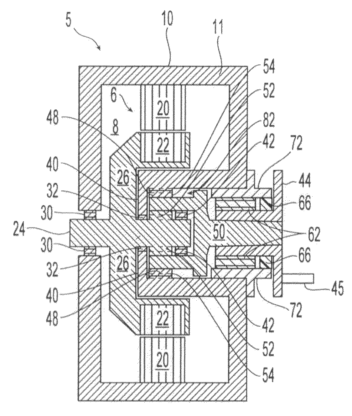
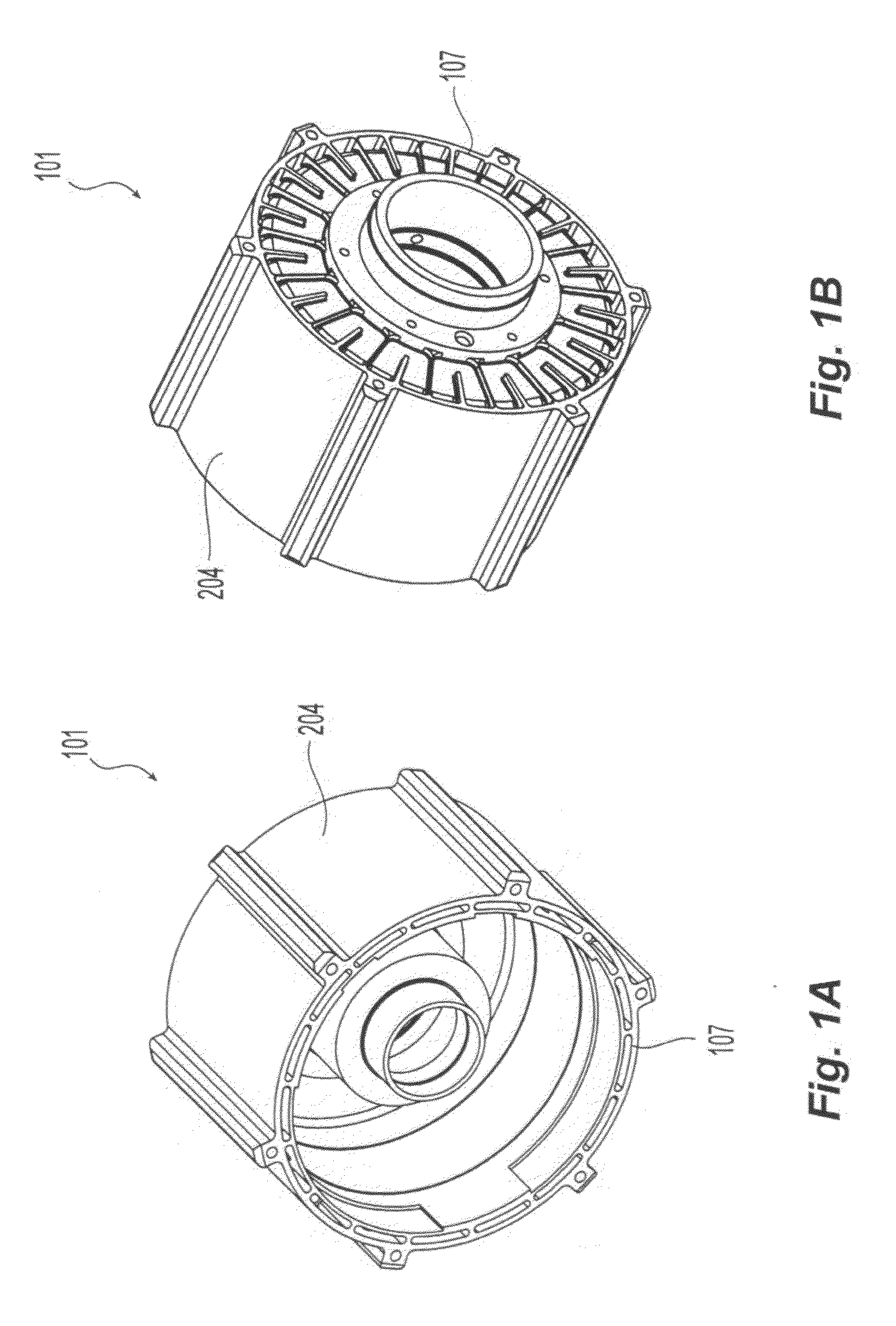
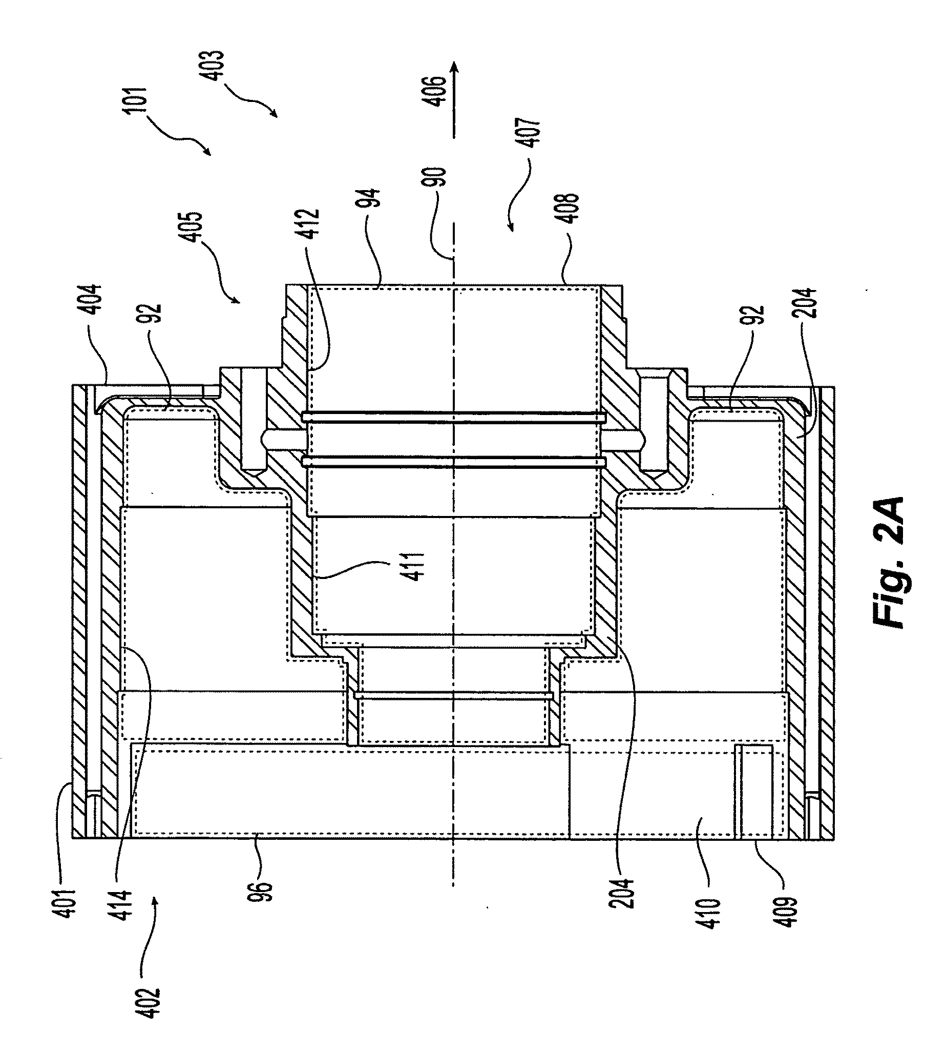
[0006]The invention provides a housing for a wheel motor that has a continuous and unitary housing wall separating the electrical motor components from the mechanical transmission components of the wheel motor, while providing a structure to support the wheel motor within a vehicle with engagement to a suspension system, to a wheel, and to support a brake caliper, and further providing a cooling structure to transfer heat away from the motor components. Preferably, the electrical motor components include a stator and a rotor with the rotor engaging a axially central motor shaft communicating with the mechanical transmission components through an axially-disposed port defined by the housing wall. The mechanical transmission components preferably include a planetary gear system disposed about the motor shaft and communicating with the electrical motor components, and preferably include an output shaft that engages a wheel mount that turns a wheel surrounding the wheel motor and that shares a common longitudinal axis with the rotor, motor shaft, and wheel mount. The housing is preferably reinforced to convey load forces through the housing wall to support the wheel motor within a vehicle while connected to a suspension system at suspension mounts and the wheel at the wheel mount while maximizing the radial size of the stator disposed within the interior of the wheel surrounding the wheel motor and while maintaining the axial position of the planetary gears and load bearings of the mechanical transmission within the inner diameter of the stator and at a common axial position as the stator.

Problems solved by technology

It is believed that the additional weight and complexity of the drive train and axle reduces the efficiency of the hybrid vehicle and electric motor, and reduces the carrying capacity and range of the hybrid vehicle.
It is also believed that existing motors that are housed in a wheel do not maximize the size of the stator located within the wheel, and also provide systems that do not allow for the assembly and disassembly of transmission and load-bearing components separately from the motor components.

Method used


Image

  • Wheel motor
  • Wheel motor
  • Wheel motor

Examples


Embodiment Construction

[0035]The invention provides a housing for a wheel motor that has a continuous and unitary housing wall separating the electrical motor components from the mechanical transmission components of the wheel motor, while providing a structure to support the wheel motor within a vehicle with engagement to a suspension system, to a wheel, and to support a brake caliper, and further providing a cooling structure to transfer heat away from the motor components. Preferably, the electrical motor components include a stator and a rotor with the rotor engaging a axially central motor shaft communicating with the mechanical transmission components through an axially-disposed port defined by the housing wall. The mechanical transmission components preferably include a planetary gear system disposed about the motor shaft and communicating with the electrical motor components, and preferably include an output shaft that engages a wheel mount that turns a wheel surrounding the wheel motor and that s...


PUM


Abstract

A wheel motor with an housing enclosing the motor and defining a cylindrical cavity extending into a space at the center of the motor, with the motor and the cavity separated from each other by the housing. The cavity containing, at least in part, a transmission engaging a shaft of the motor, and a wheel bearing supporting the load of a wheel engaging a wheel mount connected to the transmission. The transmission preferably includes a planetary gear surrounded by the motor in the cavity.

Description

RELATED APPLICATIONS[0001]This application claims benefit of priority to U.S. Provisional Patent Application No. 60 / 912,896 filed Apr. 19, 2007 which is incorporated by reference in its entirety.TECHNICAL FIELD[0002]The invention relates to electric motors and, specifically, to an electric motor housed within a wheel of a vehicle.BACKGROUND ART[0003]Existing hybrid vehicles use a single electric motor that provides torque to a drive train connected to the wheels of the vehicle, in a manner similar to how a gas-powered engine provides torque through a drive shaft and axle. It is believed that the additional weight and complexity of the drive train and axle reduces the efficiency of the hybrid vehicle and electric motor, and reduces the carrying capacity and range of the hybrid vehicle. It is also believed that existing motors that are housed in a wheel do not maximize the size of the stator located within the wheel, and also provide systems that do not allow for the assembly and disa...

Claims


Application Information

Patent Timeline
IPC IPC(8): B60K1/00H02K7/116
CPCB60K7/0007B60K17/046B60K2007/0038H02K7/14H02K7/085H02K7/116B60K2007/0092B60L2220/44Y02T10/64
Inventor KENDALL, TODD A.PAVLOV, KEVIN J.SCIRIHA, ADAM
Owner BLUWAV SYST LLC
Learn More