
Transfer jig for bracket or tube, manufacturing and using method thereof

a technology of transfer jigs and brackets, which is applied in the direction of computer control, program control, instruments, etc., can solve the problems of inconvenient manufacturing, inconvenient use of materials, so as to improve the credibility, reduce the attachment time of brackets, and improve the effect of reproduction or realization

Inactive Publication Date: 2010-07-29
LEE JOONHO
View PDF9 Cites 19 Cited by
  • Summary
  • Abstract
  • Description
  • Claims
  • Application Information

AI Technical Summary

Benefits of technology

[0011]Accordingly, it is an aspect of the present invention to provide a transfer jig for a bracket or tube to maintain high precision in attaching a bracket or tube to teeth, a manufacturing and using method thereof.
[0012]Also, it is another aspect of the present invention to provide a transfer jig for a bracket or tube to reduce attachment time of a bracket of a tube, a manufacturing and using method thereof.
[0013]Also, it is another aspect of the present invention to provide a transfer jig for a bracket or tube to provide excellent reproduction or realization and improve credibility.
[0014]Also, it is another aspect of the present invention to provide a transfer jig for a bracket or tube to improve adhesion, manufacturing and using methods thereof.
[0015]Further, it is another aspect of the present invention to provide a transfer jig for a bracket or tube which is cost effective and improves user's convenience, manufacturing and using methods thereof.

Problems solved by technology

However, the indirect attachment using the mold such as the plaster is less precise and takes a lot of attachment time and overall operation time.
Also, the material may be overused.

Method used


Image

  • Transfer jig for bracket or tube, manufacturing and using method thereof
  • Transfer jig for bracket or tube, manufacturing and using method thereof
  • Transfer jig for bracket or tube, manufacturing and using method thereof

Examples


Embodiment Construction

[0032]Reference will now be made in detail to the embodiments of the present general inventive concept, examples of which are illustrated in the accompanying drawings, wherein like reference numerals refer to like elements throughout. The embodiments are described below in order to explain the present invention by referring to the figures.

[0033]Hereinafter, a transfer jig for a bracket or a tube and a method of transferring the bracket according to the present invention will be described in detail with reference to drawings.

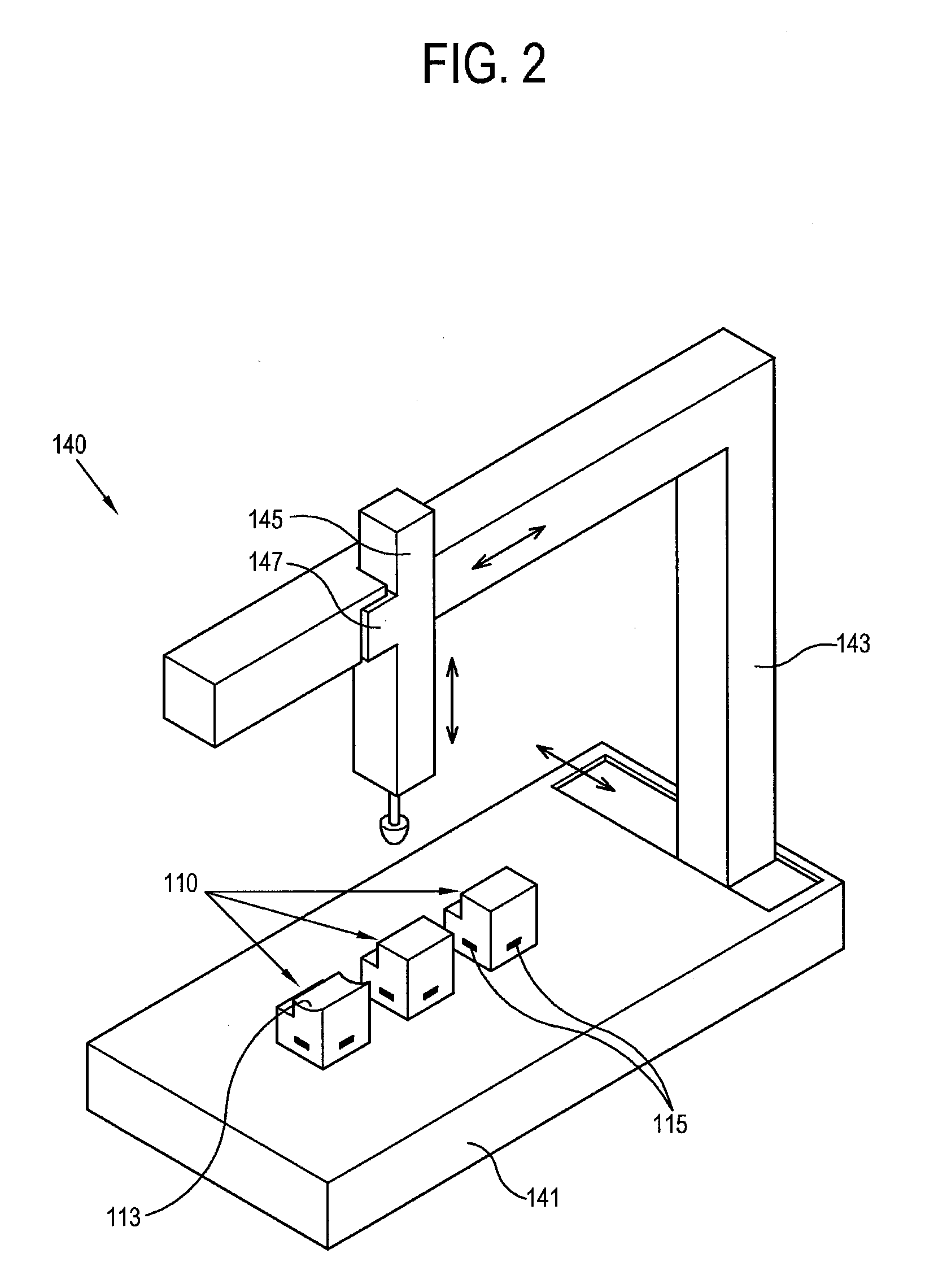
[0034]Hereinafter, an orthodontic device which uses a computer aided design (CAD) or computer aided manufacture (CAM) of an indirect attachment will be described as an example. Equipment which measures or manufactures a transfer jig for a bracket or tube includes a three-dimensional measurement program and an equipment controlled by a computerized numerical control (CNC) to manufacture the transfer jig for the bracket or tube. Among the CNC equipment, a multi-axi...


PUM


Abstract

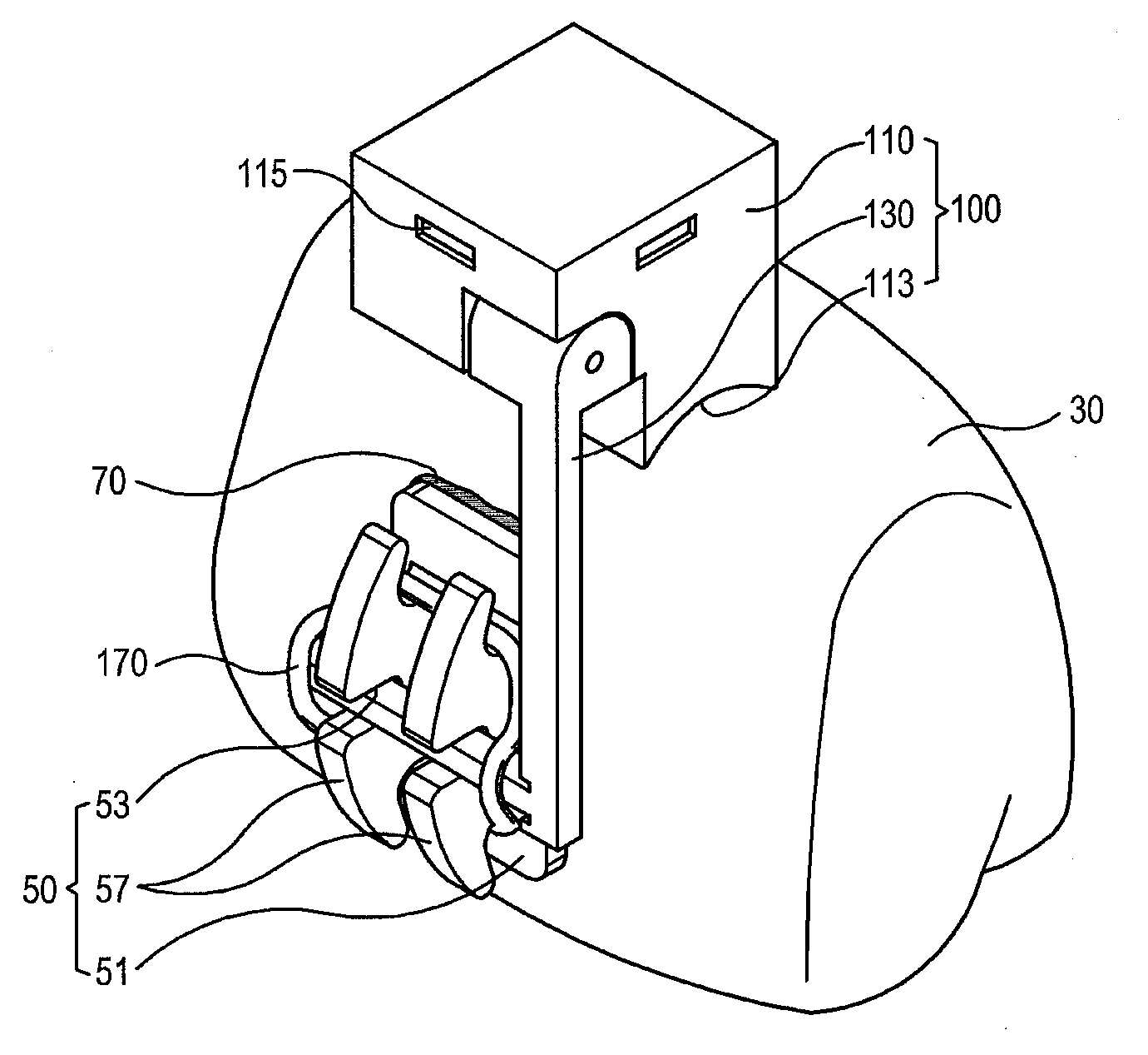
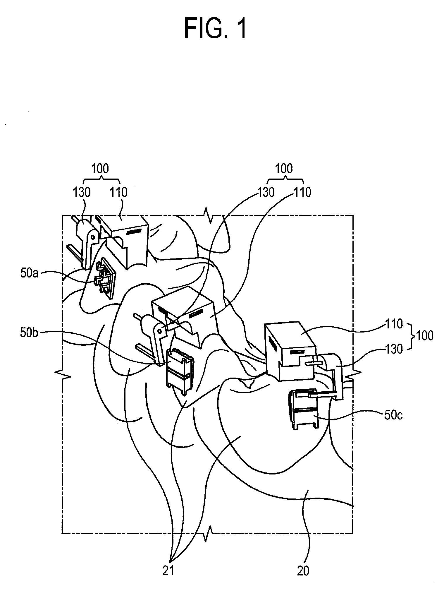
The present invention relates to a transfer jig for a bracket or a tube to perform an orthodontic operation to an actual tooth of a patient by an indirect attachment using an electronic mold, the transfer jig comprising a fixing unit which has a fixing base including a contact surface corresponding to the actual teeth; and a moving unit which has a first side coupled with the fixing unit and a second side detachably attached to at least one of the bracket and the tube. That is, the fixing unit is manufactured by a small / high precision CNC equipment installed in individual dental clinics. The moving unit is attached to a slot of the bracket or tube in the same direction as the coupling direction of the arch wire. The moving unit is rotatably coupled with the fixing unit.

Description

FIELD OF THE INVENTION[0001]Apparatuses and methods consistent with the present invention relate to a transfer jig for a bracket or a tube, a manufacturing and using method thereof, and more particularly, to a transfer jig for a bracket or a tube which improves a method of measuring, manufacturing and using a bracket or a tube with a computer aided design (CAD) and computer aided manufacture (CAM) of indirect attachment of an orthodontic device, a manufacturing and using method thereof.BACKGROUND ART[0002]A set of teeth in normal occlusion has an appropriate shape and is required to be positioned with a specific requirement. From a front tooth to a molar, the height is gradually reduced. Only if the front tooth, a canine tooth and the molar are arranged at an appropriate angle of inclination, people can chew, speak, swallow well and have a good appearance.[0003]To correct the mal-aligned or mal-occluded tooth, a bracket or a tube having an orthodontic wire is attached to a front or ...

Claims


Application Information

Patent Timeline
Patent Type & Authority Applications(United States)
IPC IPC(8): A61C7/02G06F17/50G05B19/4097
CPCA61C7/146A61C7/14A61F7/00
Inventor LEE, JOONHO
Owner LEE JOONHO
Learn More