Gastrointestinal implant and methods for use

a technology for gastrointestinal implants and gastrointestinal tubes, applied in the field of gastrointestinal implants and methods for use, can solve the problems of increased risk of death, increased recovery time, and increased obesity-related health problems, and achieve the effect of reducing the diameter and reducing the diameter

Inactive Publication Date: 2010-07-29
LAUFER MICHAEL D
View PDF76 Cites 33 Cited by
  • Summary
  • Abstract
  • Description
  • Claims
  • Application Information

AI Technical Summary

Benefits of technology

[0011]Additional variations include one or more kits for bypassing intestinal fluids from the digestive tract comprising a scope-type device and an intestinal implant in accordance with those variations described herein.
[0012]In certain embodiments, an intestinal implant for preventing the interaction of fluid with a portion of the small intestines comprising a body means for diverting fluid from the opening in the intestines, a passage means or conduit for conveying fluid to a distal location in the intestines, and a securing means for securing the implant to a wall of the intestines is provided. The securing means may comprise the fasteners discussed herein or may comprise other methods of securing the implant to the intestinal wall as also discussed herein.
[0013]In certain embodiments, a device for diverting fluid from a duct in a wall of the GI tract, e.g., a wall of a small intestine, is provided. The device may include a support frame having a first cuff, a second cuff, a central portion and a passageway extending through the central portion and / or between the first and second cuffs. The central portion may have a reduced diameter relative to a diameter of the first and / or second cuffs and at least one opening in a side-wall of the central portion. The first and second cuffs may be expandable with the second cuff being configured to form a fluid tight seal against the wall of the small intestine at a location distal to a duct opening and the first cuff being configured to form a fluid tight seal against the wall of the small intestine at a location proximal to the duct opening. The first and second cuffs in combination with an exterior wall of the central portion and a wall of the small intestine define a reservoir for receiving fluid from the duct.
[0014]A conduit may be coupled to the side-wall of the central portion of the support frame. At least a portion of the conduit extends within the passageway and the conduit may have a first end, a second end, a side-wall having an opening, and a lumen. The opening in the side-wall of the conduit may be coupled, connected or secured to the opening in the side-wall of the central portion such that fluid entering the opening in the side-wall of the central portion from the reservoir or directly from the duct passes through the opening in the side-wall of the conduit and into the conduit lumen. A diameter of the conduit may be smaller than a diameter of the passageway such that foods and other digestive substances may pass through the passageway and past the conduit without entering the conduit or entering the conduit in a reduced manner.
[0015]In certain embodiments, a method for diverting fluid from a duct in a wall of the small intestine is provided. The method may include inserting a device into the small intestine. The device includes a support frame having a first cuff, a second cuff, a central portion and a passageway extending between the first and second cuffs and / or through the central portion. The central portion may have a reduced diameter relative to a diameter of the first and / or second cuffs and at least one opening in a side-wall of the central portion. A conduit may be coupled to the side-wall of the central portion where at least a portion of the conduit extends within the passageway and a diameter of the conduit is smaller than a diameter of the passageway. The conduit may have a first end, a second end, a side-wall having an opening, and a lumen. An opening in the side-wall of the conduit may be coupled, connected or secured to the opening in the side-wall of the central portion such that fluid entering the opening in the side-wall of the central portion passes through the opening in the side-wall of the conduit and into the conduit lumen.
[0016]The device may be positioned within the small intestine such that the second cuff is located distal to a duct opening and the first cuff is located proximal to the duct opening. The first and second cuffs may be expanded or fit against the wall of the small intestine such that the second cuff forms a fluid tight seal against the wall of the small intestine distal to the duct opening and the first cuff forms a fluid tight seal against the wall of the small intestine proximal to the duct opening. The first and second cuffs in combination with an exterior wall of the central portion and a wall of the small intestine define a reservoir for receiving fluid from the duct. Fluid can be diverted or rerouted from the reservoir or directly from the duct opening through the opening in the side-wall of the central portion and into the opening in the side-wall of the conduit. The fluid passes from the opening in the side-wall of the conduit, through the conduit lumen and drains from the second end of the conduit positioned within the GI tract or small intestine at a distance from the opening in the side-wall of the conduit, the opening in the central portion, and / or the first end of the conduit. During use, food and other digestive substances may pass through the passageway and past the conduit without entering the conduit or where substances enter the conduit in a reduced manner.

Problems solved by technology

The incidence of obesity in the United States is significantly increasing causing an associated increase in obesity-related health problems.
However, while there may be a considerable number of individuals that are markedly overweight, a fraction of these individuals are currently eligible for surgery to reconstruct their gastrointestinal (GI.) tract in order to control their weight.
Because these procedures often involve invasive surgery, the recuperation time is significant not to mention the possibility of complications which include the risk of death.
Obviously such a high risk of death justifies the use of these surgical procedures.
Both methods cause weight loss through bypass by reducing the effective length of intestine available for the absorption of food and the stomach is reduced in size so that the patient cannot eat a lot of food.
However, both methods require anesthesia (usually general), a prolonged recovery time, and are not reversible once the target weight of the patient is reached.
This procedure also has numerous complications including rupture of the staple line, infection of the surgical incision, post operative hernias and the like.
Moreover, due to the large amount of fat tissue in the anterior abdominal wall in the typical patient on whom this procedure is performed, poor healing of the operative wound may result.
Furthermore prolonged post-operative bed rest after such extensive surgery predisposes obese patients to the development of deep vein thrombosis and possible pulmonary emboli, some with a potentially lethal outcome.

Method used


Image

  • Gastrointestinal implant and methods for use
  • Gastrointestinal implant and methods for use
  • Gastrointestinal implant and methods for use

Examples


Embodiment Construction

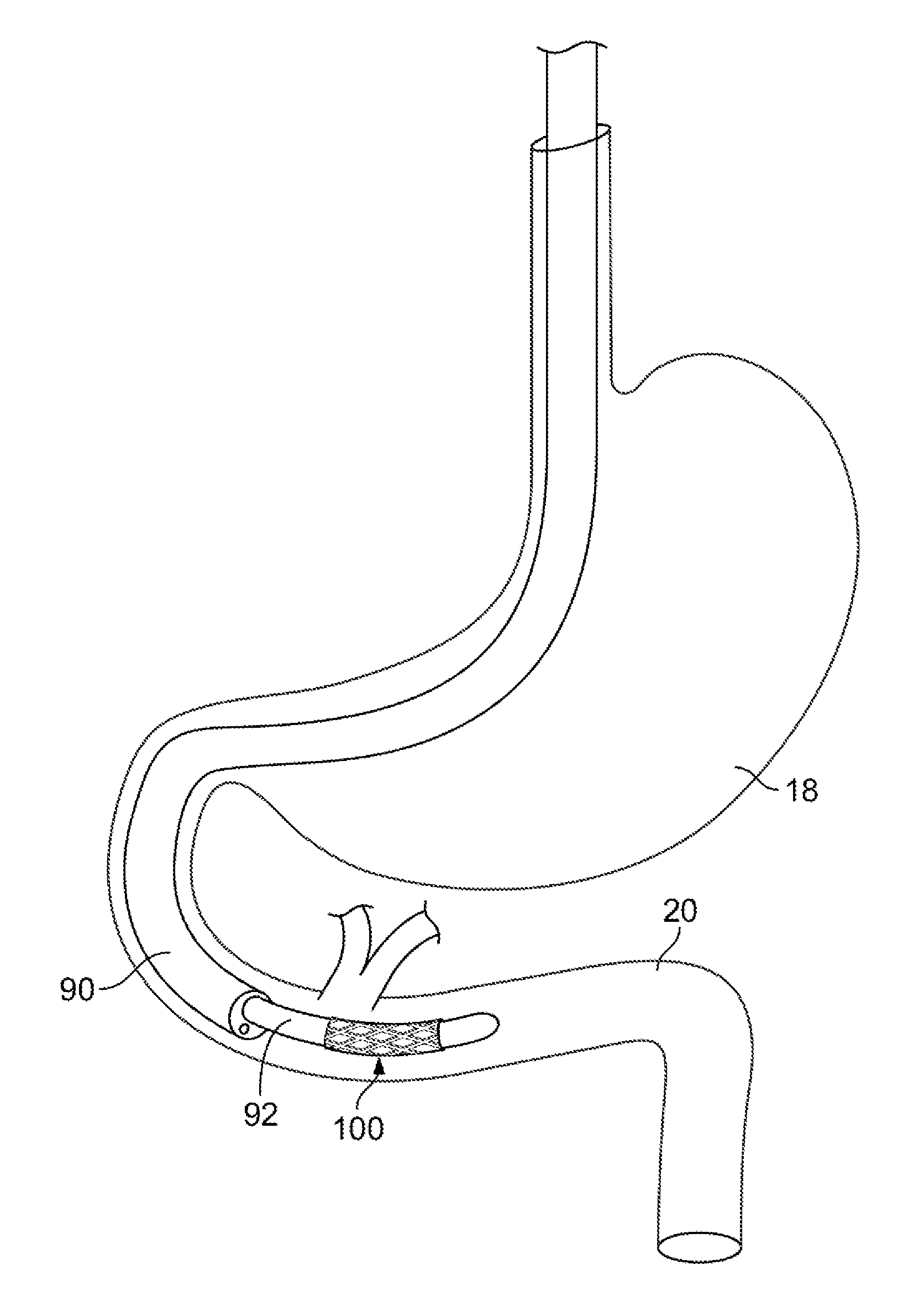
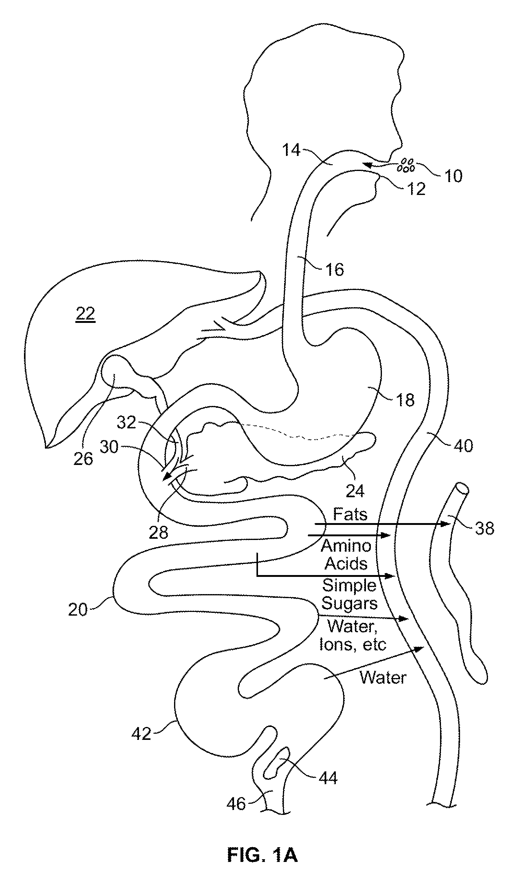
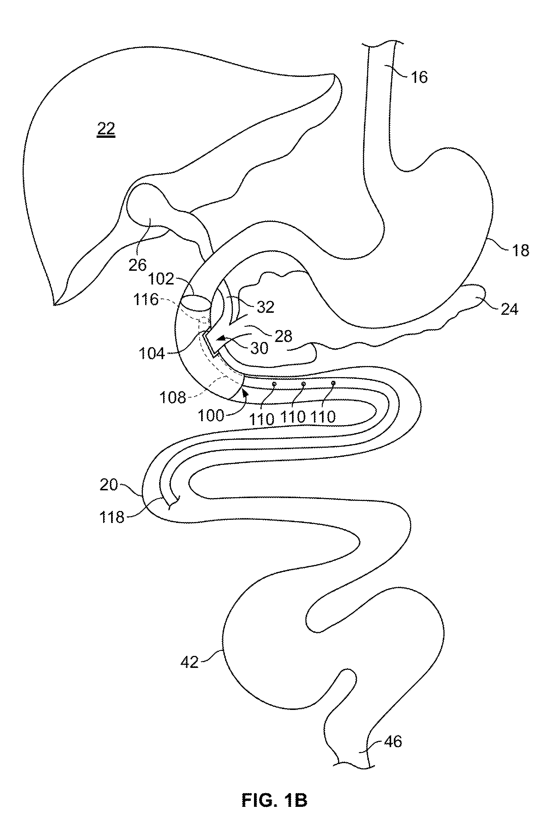
[0032]Various embodiments are described herein in the context of a minimally invasive gastrointestinal bypass. Those of ordinary skill in the art will realize that the following detailed description is illustrative only and is not intended to be in any way limiting. Other embodiments will readily suggest themselves to such skilled persons having the benefit of this disclosure. Reference will now be made in detail to implementations and embodiments as illustrated in the accompanying drawings. The same reference indicators will be used throughout the drawings and the following detailed description to refer to the same or like parts.

[0033]In the interest of clarity, not all of the routine features of the implementations described herein are shown and described. It will, of course, be appreciated that in the development of any such actual implementation, numerous implementation-specific decisions must be made in order to achieve the developer's specific goals, such as compliance with ap...


PUM


Abstract

Methods and devices for modifying the location at which bodily fluids interact with nutrients in a gastrointestinal tract. The methods and devices utilize a conduit configured to divert bodily fluids from an entrance within a gastrointestinal tract to a location downstream from the entrance.

Description

CROSS-REFERENCE TO RELATED APPLICATIONS[0001]This application is a continuation-in-part of U.S. patent application Ser. No. 12 / 203,030 filed Sep. 2, 2008, which is a continuation of PCT International Application No. PCT / US2007 / 063140 filed Mar. 2, 2007 which claims the benefit under 35 U.S.C. §119(e) of U.S. Provisional Application No. 60 / 779,062 filed Mar. 2, 2006. The contents of all of these applications are incorporated herein by reference in their entirety.BACKGROUND OF THE INVENTION[0002]The incidence of obesity in the United States is significantly increasing causing an associated increase in obesity-related health problems. Because of this trend, efforts to control obesity are gaining the increased attention of both the medical community and the general public. However, while there may be a considerable number of individuals that are markedly overweight, a fraction of these individuals are currently eligible for surgery to reconstruct their gastrointestinal (GI.) tract in or...

Claims


Application Information

Patent Timeline
Patent Type & Authority Applications(United States)
IPC IPC(8): A61M1/00
CPCA61F2/07A61F2/24A61F2/91A61F5/0076A61B17/1114A61F2002/30329A61F2220/0025A61F2250/0039A61F2002/068A61F2/2476
Inventor LAUFER, MICHAEL D.
Owner LAUFER MICHAEL D
Why Eureka
Try Eureka