
Exhaust gas cleaning device, exhaust system and clamp connection

Active Publication Date: 2010-08-05
EBERSPACHER EXHAUST TECH GMBH & CO KG
View PDF8 Cites 0 Cited by
  • Summary
  • Abstract
  • Description
  • Claims
  • Application Information

AI Technical Summary

Benefits of technology

[0004]The present invention pertains to the object of providing an exhaust gas cleaning device or an exhaust system equipped therewith or a clamp connection as an improved embodiment, which is characterized especially in that it can be embodied at a relatively low cost and shall, in addition, guarantee a comparatively long service life for the clamp connection.
[0006]The present invention is based on the general idea of providing—on two tubular bodies, which shall be detachably connected to one another by means of a clamp connection—a radially outwardly projecting ring collar each, which are in contact with a common sealing ring on sides facing each other and at which the particular clamp is supported on sides facing away from each other via a separate ring body each. Such ring collars can be prepared on the tubular bodies at a comparatively low cost with relatively narrow tolerances. In addition, such ring bodies can be manufactured separately from the tubular bodies at a comparatively low cost with relatively narrow tolerances. There are correspondingly comparatively narrow tolerances within the clamp connection, as a result of which a relatively symmetrical or uniform load is obtained for the sealing ring. This has an advantageous effect for the sealing action and the service life of the sealing ring and hence of the clamp connection. Even though a plurality of individual parts must be used and installed in the clamp connection being proposed, this mode of construction can be embodied at a relatively low cost, and markedly narrower tolerances can be maintained at the same time.
[0007]Corresponding to an advantageous embodiment, the ring bodies can be fastened to the particular tubular body, doing so such that they are already in contact with the particular ring collar of the tubular body on the side facing away from the sealing ring. Removal and the later remounting are simplified due to the ring body being fixed to the tubular bodies, because the ring bodies remain at the mounting site intended therefor. Suitable fixations can be embodied now at a low cost, for example, by means of welded or soldered connections, especially in the form of weld points or soldering points.
[0008]According to another advantageous embodiment, the two ring collars can have a flat contact surface each, via which they are flatly in contact with the sealing ring. Due to the flat contact between the ring collars and the sealing ring, the axial pressing forces generated by means of the clamp are distributed over a large area, as a result of which the sealing ring as a whole is loaded with a comparatively low load and above all uniformly. On the one hand, the sealing action improves hereby. On the other hand, the service life of the sealing ring increases as a result.
[0009]In another advantageous embodiment the sealing ring may be provided radially inside with a protective ring extending circumferentially in the circumferential direction. The sealing ring can be protected by this protecting ring, for example, from a thermal load caused by the hot exhaust gases flowing in the tubular bodies, which likewise prolongs the service life of the sealing ring and hence of the entire clamp connection.

Problems solved by technology

For example, particle filters may become gradually clogged by noncombustible residues.
The relatively great manufacturing tolerances of the particular clamp, on the one hand, and of the housing sections to be connected thereto, on the other hand, are often problematic in such clamp connections.
However, the manufacturing tolerances frequently lead to asymmetrical loads on the seals, as a result of which these may become leaky over time.
Undesirable pollutant emissions into the environment as well as excessive thermal loads on adjacent components may occur in case of leakage.

Method used


Image

  • Exhaust gas cleaning device, exhaust system and clamp connection
  • Exhaust gas cleaning device, exhaust system and clamp connection

Examples


Embodiment Construction

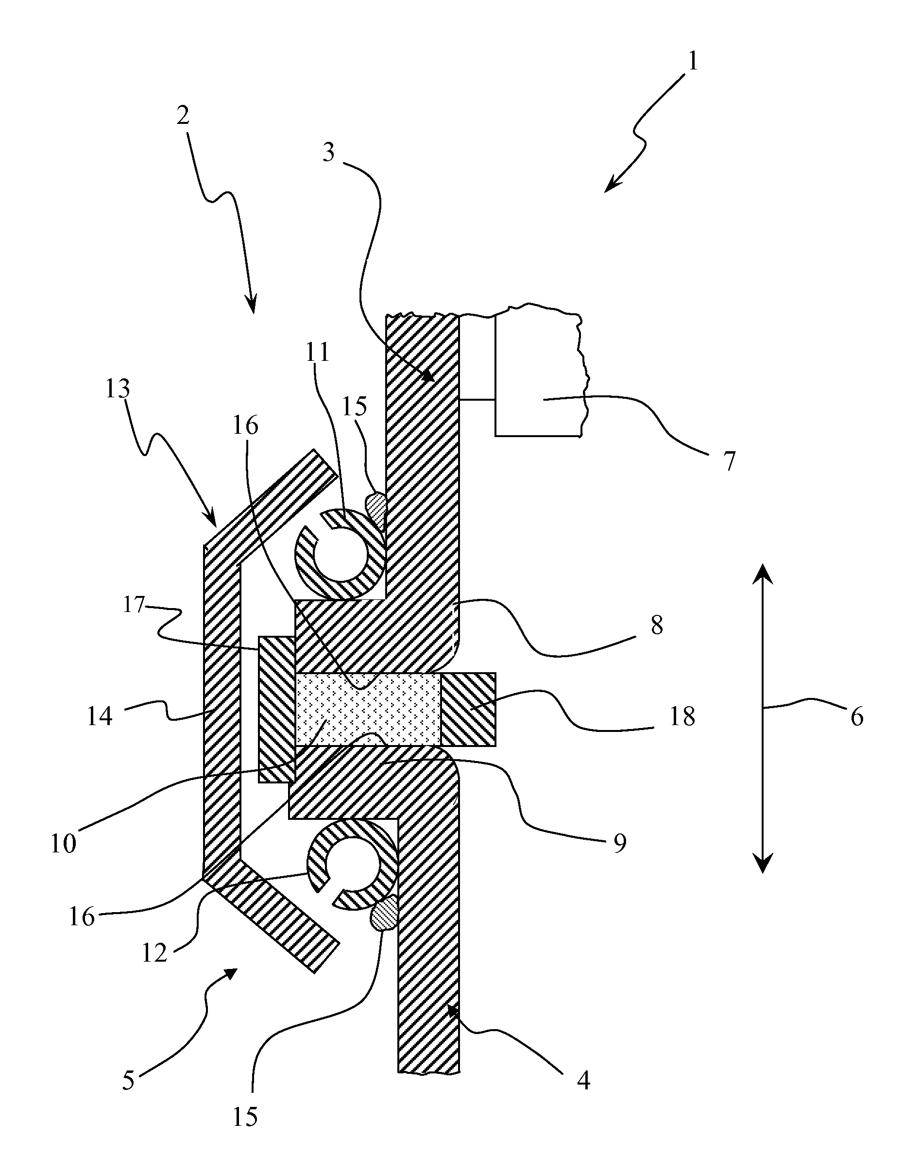
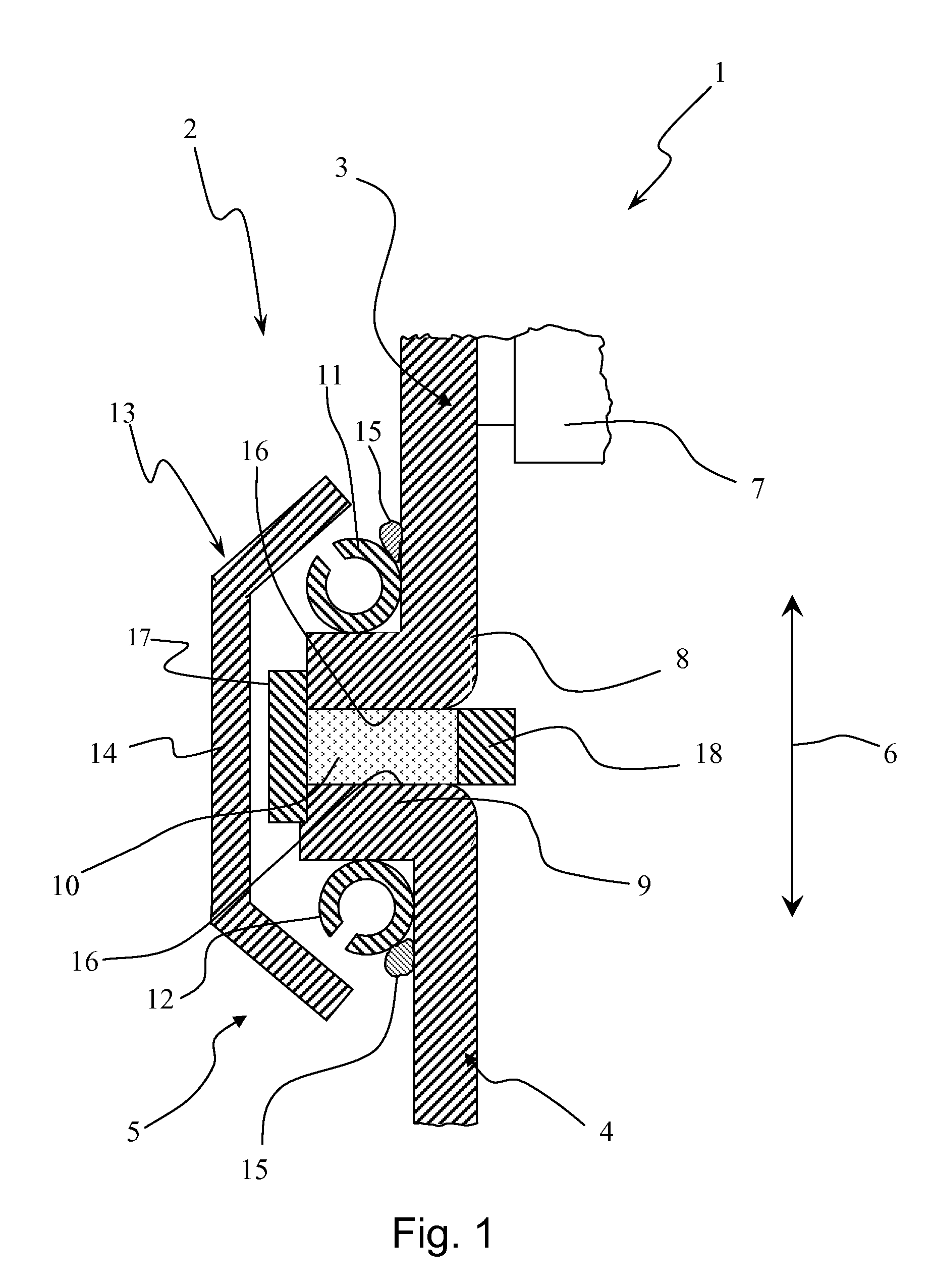
[0014]Referring to the drawing in particular, corresponding to FIG. 1, an exhaust system 1, which is shown here only partially, comprises at least one exhaust gas cleaning device 2, which is likewise shown only partially and which may be, for example, a catalytic converter or a particle filter. The exhaust system 1 is used to remove exhaust gases from an internal combustion engine, which may be arranged especially in a motor vehicle and preferably in a utility vehicle. To simplify or make possible the maintenance or replacement of at least one exhaust gas cleaning element 7 of the exhaust gas cleaning device 2 shown here only partially, at least two tubular bodies, namely, a first tubular body 3 and a second tubular body 4, are detachably connected to one another via a clamp connection 5 within the exhaust system 1 or within the exhaust gas cleaning device 2. The two tubular bodies 3, 4 extend, at least in the areas of the clamp connection 5, in parallel to a longitudinal direction ...


PUM


Abstract

An exhaust gas cleaning device (2) for an exhaust system (1) of an internal combustion engine with an exhaust gas cleaning element (7), which is arranged in a first tubular body (3), and with a second tubular body (4), to which the first tubular body (3) is detachably connected via a clamp connection (5). The clamp connection (5) includes a radially outwardly projecting first ring collar (8), formed at the first tubular body (3) and extending circumferentially in a closed form and a radially outwardly projecting second ring collar (9), formed at the second tubular body (4) and extending circumferentially in a closed form. A sealing ring (10) extends circumferentially in a closed form and is axially in contact with the first ring collar (8) and the second ring collar (9). A first ring body (11) is arranged on the outside at the first tubular body (3) and is axially in contact with the first ring collar on the side facing away from the sealing ring (10). A second ring body (12) is arranged on the outside at the second tubular body (4) and is axially in contact with the second ring collar (9) on the side facing away from the sealing ring (10). A clamp (13) extends over both the first ring body and said second ring body (11, 12) and tightens these axially towards one another.

Description

CROSS REFERENCE TO RELATED APPLICATIONS[0001]This application claims the benefit of priority under 35 U.S.C. §119 of German Patent Application DE 10 2009 007 391.4 filed Feb. 5, 2009, the entire contents of which are incorporated herein by reference.FIELD OF THE INVENTION[0002]The present invention pertains to an exhaust gas cleaning device for an exhaust system of an internal combustion engine, especially of a motor vehicle. The present invention pertains, in addition, to an exhaust system equipped with such an exhaust gas cleaning device as well as to a clamp connection for use in such an exhaust system or in such an exhaust gas cleaning device.BACKGROUND OF THE INVENTION[0003]Exhaust systems of internal combustion engines usually contain a plurality of exhaust gas cleaning devices, for example, catalytic converters, particle filters and the like. It may be necessary in case of high mileages of the internal combustion engines equipped therewith to replace a cleaning element of suc...

Claims


Application Information

Patent Timeline
IPC IPC(8): F01N3/00F16J15/02F16L23/16
CPCF01N13/1805F01N13/1838F16L23/04F01N2450/18F01N13/1844
Inventor DATZ, WOLFGANGKRAUSE, MICHAEL
Owner EBERSPACHER EXHAUST TECH GMBH & CO KG
Learn More