

Cnt-infused glass fiber materials and process therefor
a technology of glass fiber materials and carbon nanotubes, applied in the field of fiber materials, can solve the problems of affecting increasing surface area, and reducing the tensile strength of glass fiber materials
- Summary
- Abstract
- Description
- Claims
- Application Information
AI Technical Summary
Problems solved by technology
Method used
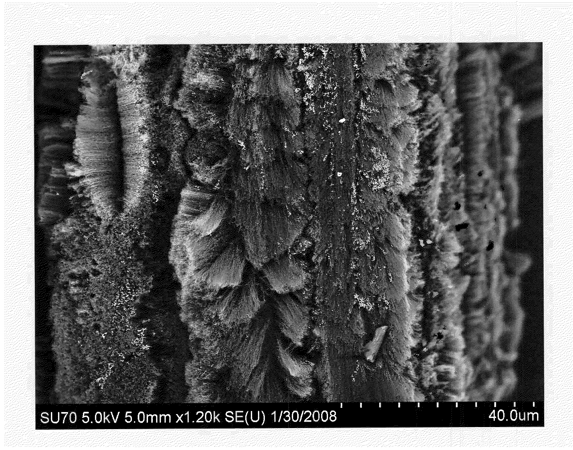
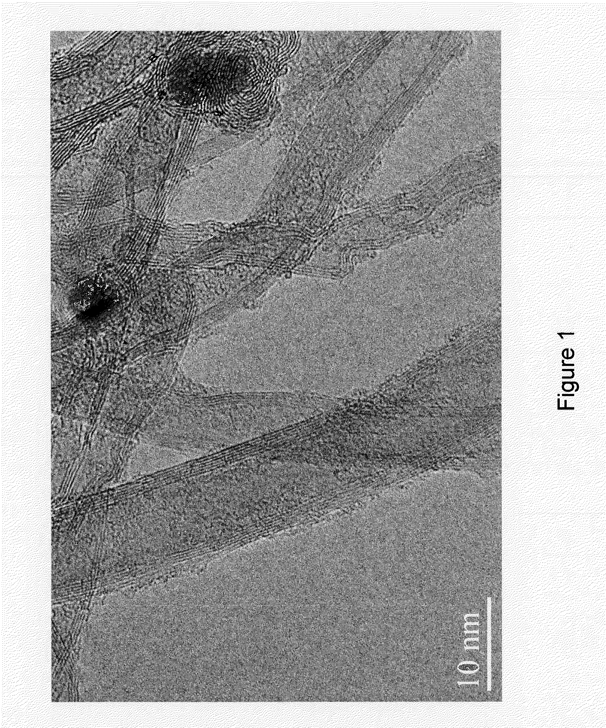
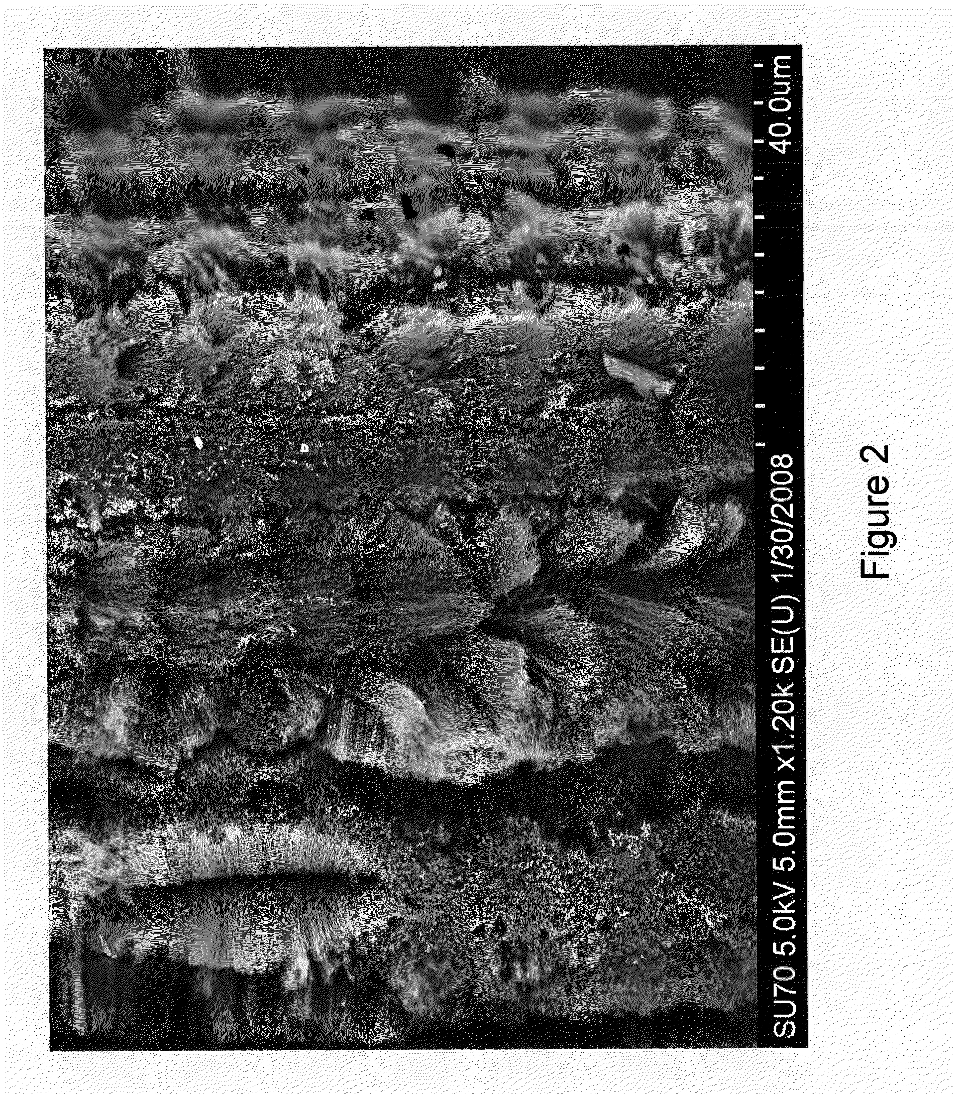
Image

Examples
example i
[0132]This example shows how a glass fiber material can be infused with CNTs in a continuous process for applications requiring improved shear strength. In this case, a high density array of shorter CNTs is desirable.
[0133]FIG. 8 depicts system 800 for producing CNT-infused fiber in accordance with the illustrative embodiment of the present invention. System 800 includes a glass fiber material payout and tensioner system 802, CNT-infusion system 812, and fiber winder 824, interrelated as shown.
[0134]Payout and tension system 802 includes payout bobbin 804 and tensioner 806. The payout bobbin holds fiber spools and delivers glass fiber material 801 to the process at a linespeed of 9 ft / min; the fiber tension is maintained within 1-5 lbs via tensioner 806. Payout and tension station 802 is routinely used in the fiber industry; those skilled in the art will be familiar with their design and use.
[0135]Tensioned fiber 805 is delivered to CNT-infusion system 812. Station 812 includes cata...
example ii
[0139]This example shows how a nascent glass fiber material can be infused with CNTs in a continuous process for applications requiring improved electrical and / or thermal conductivity. In this case, the maximum loading of long CNTs is targeted.
[0140]FIG. 9 depicts system 900 for producing CNT-infused fiber in accordance with the illustrative embodiment of the present invention. System 900 includes a glass fiber production system 902, CNT-infusion system 912, and fiber winder 924, interrelated as shown.
[0141]Glass fiber production system includes a molten glass reservoir 905 and a extrusion die 910 used to draw nascent glass material 901 to a 15 micron diameter. In this example, an E-glass fiber is extruded at a rate of 1 ft / min.
[0142]Nascent fiber 915 is delivered to CNT-infusion system 912. CNT-infusion system 912 includes catalyst application system 920 and micro-cavity CVD based CNT infusion station 925.
[0143]In this illustrative example, the catalyst solution is applied via a sp...
example iii
[0146]This example demonstrates the CNT-Infusion of glass fiber in a continuous process for applications requiring improved tensile strength, where the system is interfaced with subsequent resin incorporation and winding process. In this case, a length CNT greater than 10 microns is desirable.
[0147]FIG. 10 depicts a further illustrative embodiment of the invention wherein CNT-infused fiber is created as a sub-operation of a filament winding process being conducted via filament winding system 1000.
[0148]System 1000 comprises glass fiber material creel 1002, carbon nanotube infusion system 1012, CNT alignment system 1005, resin bath 1028, and filament winding mandrel 1032, interrelated as shown. The various elements of system 1000, with the exception of carbon nanotube infusion system 1026 and CNT alignment system 1005, are present in conventional filament winding processes. The main element of the process and system depicted in FIG. 10 is the carbon nanotube infusion section 1026, wh...
PUM
| Property | Measurement | Unit |
|---|---|---|
| operating speeds | aaaaa | aaaaa |
| length | aaaaa | aaaaa |
| length | aaaaa | aaaaa |
Abstract
Description
Claims
Application Information