
Oil supply system for internal combustion engine with dual mode pressure limiting valve

a technology of internal combustion engine and oil supply system, which is applied in the direction of pressure lubrication, lubrication elements, auxilary lubrication, etc., can solve the problems of low oil pressure, low fuel consumption of engine, and inability to operate electrically operated valves in a fail-safe position, so as to reduce engine fuel consumption and minimize parasitic losses

Active Publication Date: 2010-08-05
FORD GLOBAL TECH LLC
View PDF17 Cites 27 Cited by
  • Summary
  • Abstract
  • Description
  • Claims
  • Application Information

AI Technical Summary

Benefits of technology

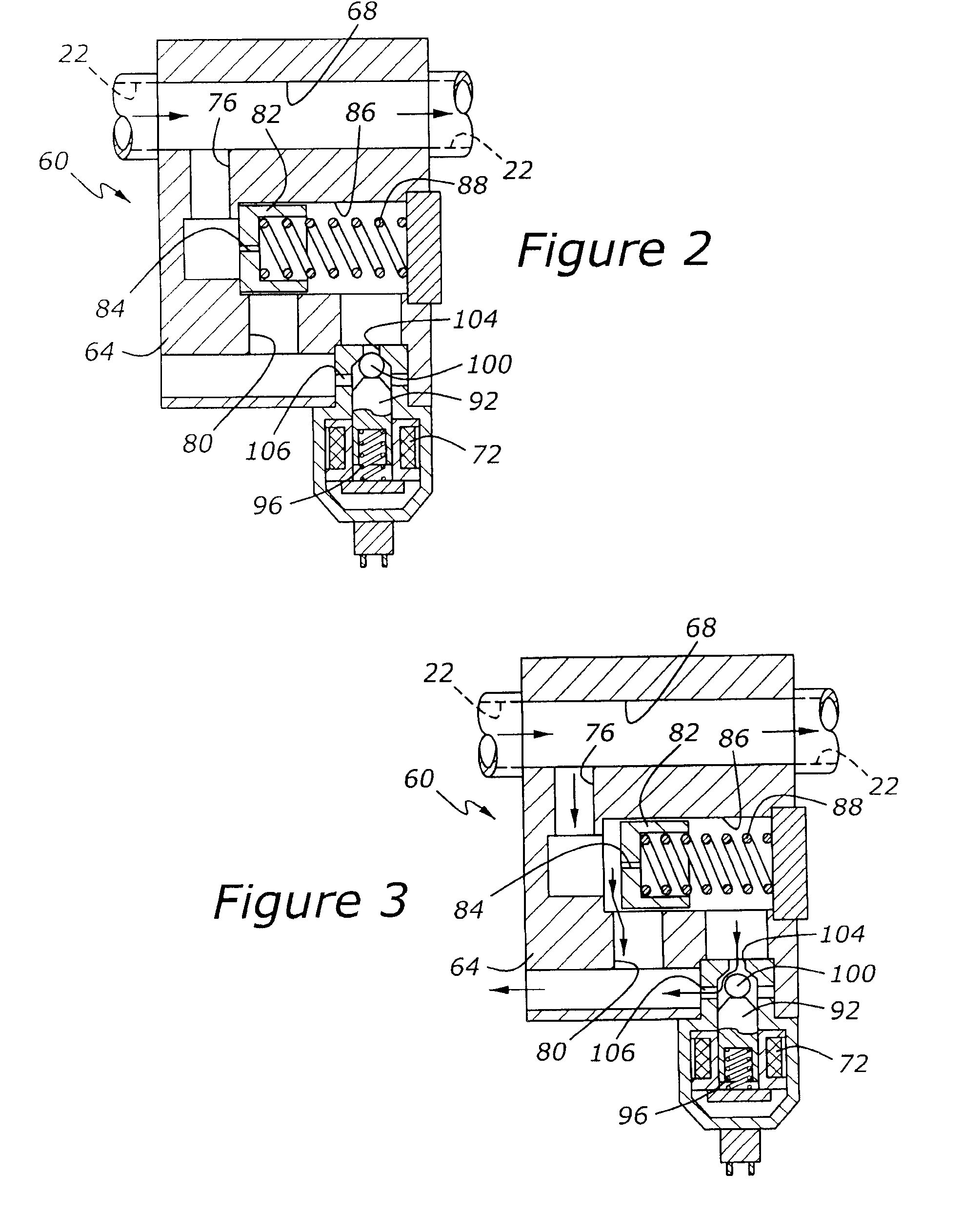
[0010]It is an advantage of a lubricating oil supply system according to the present invention that engine fuel consumption may be reduced by minimizing parasitic losses associated with an engine driven lubricating oil pump, while at the same time safeguarding the engine's integrity, by using a piloted pressure relief valve having a normally closed pilot valve, such that if the pilot valve operating system fails, the engine oil pressure will be maintained at a safe level for all engine operating modes and regimes.
[0011]It is another advantage of a system according to the present invention that the piloted pressure relief valve of the present invention may be mounted externally upon the engine, as opposed to the known conventional practice of mounting of relief valves deep inside an engine, such as in an engine oil pump, rendering such valves relatively inaccessible for service purposes.
[0012]It is yet another advantage of a system according to the present invention that the piloted pressure relief valve of the present invention may be located downstream from an oil filter, thereby protecting the pressure controller from oil-borne contamination.
[0013]It is yet another an advantage of a system according to the present invention that the inventive piloted pressure relief valve has a dual mode feature, whereby the piloted valve may be used to limit maximum lubrication system pressure in the event that a primary relief valve fails in a closed position.
[0014]It is yet another an advantage of a system according to the present invention that flow of lubricating oil through an engine will not be diminished when the present dual mode valve is not operating in a pressure limiting mode.

Problems solved by technology

Unfortunately, this causes the lubrication pump's energy consumption to be higher than would otherwise be ideal, because in many operating regimes, only a reduced volume and pressure of oil is required by the engine.
This system suffers from the drawback that the electrically operated valve does not have a fail-safe position.
In the event that the electrically operated valve fails in an open position, only minimal oil pressure would be available to sustain the engine, and such minimal oil pressure would undoubtedly be inadequate to support the engine during high speed and load operation.
On the other hand, if the electrically operated valve fails in a closed position, the resulting excessive oil pressure may damage or destroy the engine by causing the oil filter to rupture, with a consequent loss of all oil overboard.
In other words, any failure of the electronic valve could lead to engine failure.
In another vein, the reliability of the electrically operated valve is compromised because only unfiltered oil flowing from the oil pump passes through the valve, and foreign matter carried by the unfiltered oil may cause the valve to stick or wear excessively.

Method used


Image

  • Oil supply system for internal combustion engine with dual mode pressure limiting valve
  • Oil supply system for internal combustion engine with dual mode pressure limiting valve
  • Oil supply system for internal combustion engine with dual mode pressure limiting valve

Examples


Embodiment Construction

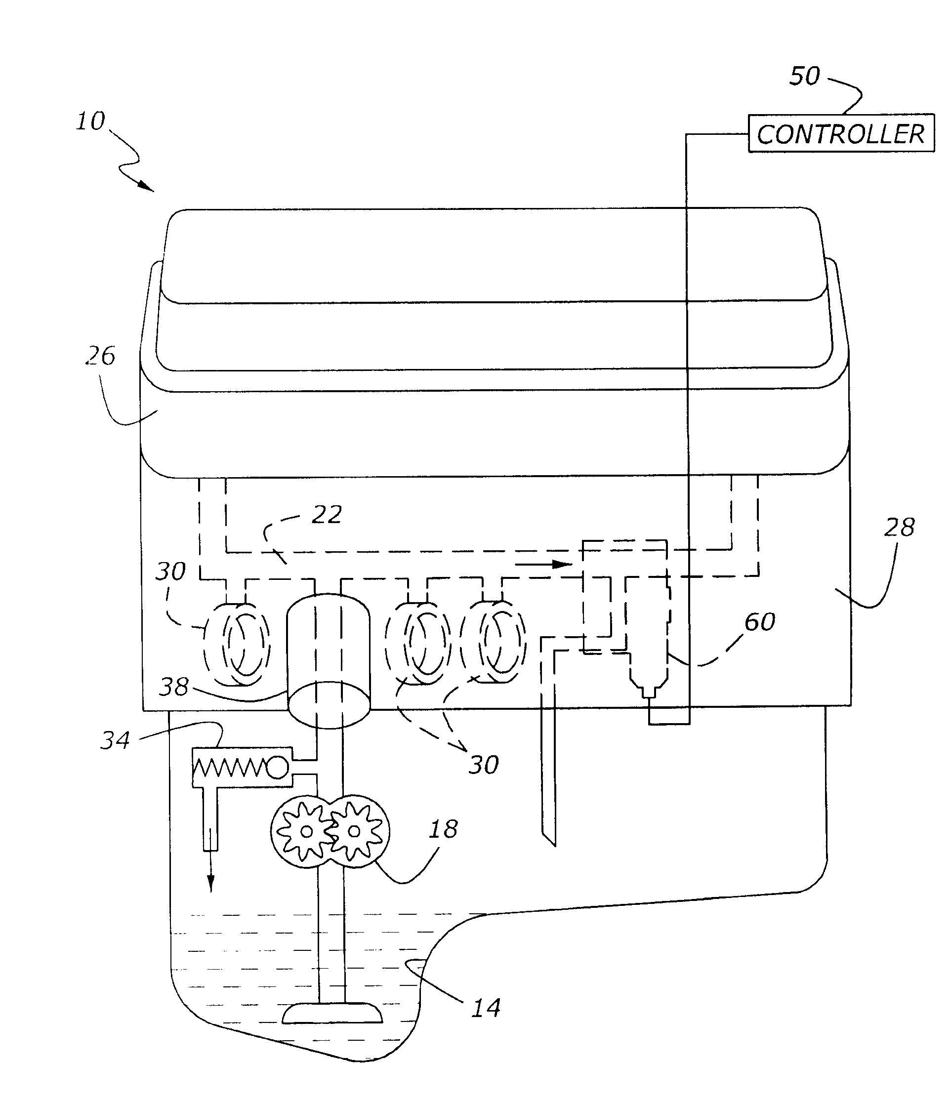
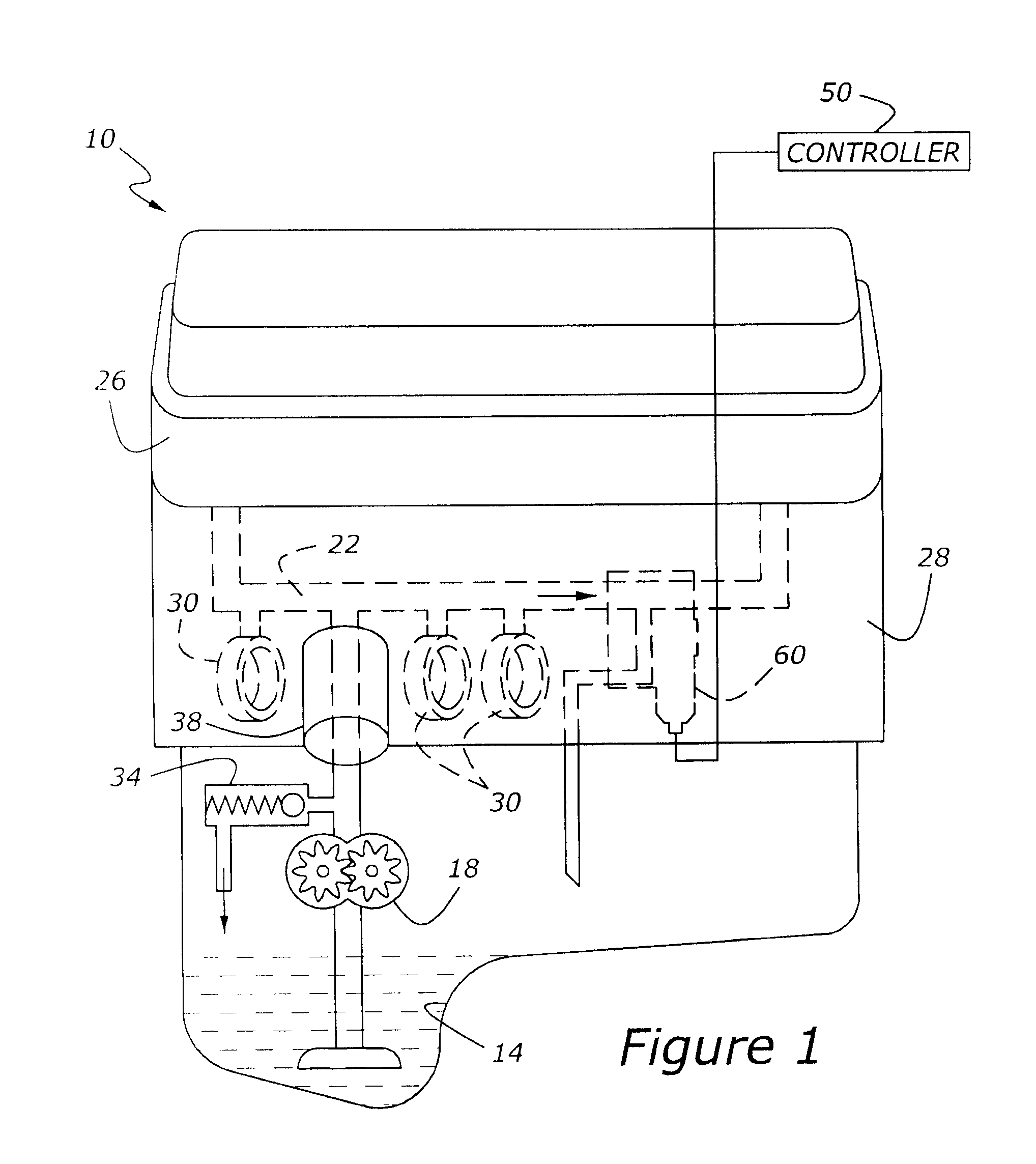
[0020]As shown in FIG. 1, an engine, 10, has an oil reservoir, 14, extending below a cylinder block, 28, and a cylinder head, 26. A lubrication distribution network, 22, is connected with an oil pump, 18. Those skilled in the art will appreciate in view of this disclosure that oil pump 18 could comprise either a gerotor type pump either driven concentrically by an engine crankshaft, or a gear pump or gerotor pump, typically mounted to the engine's cylinder block and driven by either a camshaft or another rotating component of the engine, or yet other types of pump arrangements. Such detail is committed to those wishing to employ the inventive oil supply system described and claimed herein.

[0021]The present lubricating oil supply system includes not only oil reservoir 14, oil pump 18, and lubrication distribution network 22, but also a primary pressure relief valve, 34, employed to limit the oil pressure within distribution network 22 to a maximum permissible value. In other words, p...


PUM


Abstract

A lubricating oil supply system for internal combustion engine includes an oil reservoir and oil pump connected with a lubrication distribution network including a piloted pressure relief valve which selectively controls the pressure within the distribution network to at least one pressure value that is less than the maximum pressure produced by a primary pressure relief valve associated with the oil pump, while also protecting the lubrication distribution network from an unwanted overpressure condition.

Description

CROSS REFERENCE TO RELATED APPLICATIONS[0001]None.BACKGROUND OF THE INVENTION[0002]1. Field of the Invention[0003]The present invention relates to an internal combustion engine lubrication system in which maximum pressure within the lubrication system is controlled by a dual mode pressure limiting valve.[0004]2. Related Art[0005]Pressure-lubrication has been used with automotive internal combustion engines for many years. Typically, a single pressure relief valve is used to limit the maximum pressure developed by an oil pump. The relief pressure is usually set at a fairly high value, in order to assure that the engine receives adequate lubrication in all operating regimes from idle to maximum speed-load operation. Unfortunately, this causes the lubrication pump's energy consumption to be higher than would otherwise be ideal, because in many operating regimes, only a reduced volume and pressure of oil is required by the engine.[0006]US Patent Publication 2002 / 0083915 discloses a syst...

Claims


Application Information

Patent Timeline
IPC IPC(8): F01M1/02
CPCF01M1/16
Inventor NI, BEN XUEHAI
Owner FORD GLOBAL TECH LLC
Learn More