Current driving method and circuit

Active Publication Date: 2010-08-05
ZETEX SEMICON PLC
View PDF10 Cites 22 Cited by
  • Summary
  • Abstract
  • Description
  • Claims
  • Application Information

AI Technical Summary

Benefits of technology

[0006]It is an object of certain embodiments to provide load driving methods and circuits which obviate or mitigate at least one of the problems associated with the prior art. Certain embodiments aim to provide drive methods and circuits able to drive a regulated current through a load despite varying supply voltage, load temperature, and PCB temperature. Certain embodiments aim to provide LED drive methods and circuits. Certain embodiments aim to provide drive methods and circuits able to provide control of the magnitude of regulated load current. Certain embodim

Problems solved by technology

However, a disadvantage with such known circuits operating in skip (start-stop) mode is that they can produce relatively large ripple, with the resultant emission of electromagnetic radiation, and furthermore the frequency of the skipping can be within the audio range, resulting in the coil core emitting an audible whistl

Method used


Image

  • Current driving method and circuit
  • Current driving method and circuit
  • Current driving method and circuit

Examples


Embodiment Construction

Of Embodiments Of The Invention

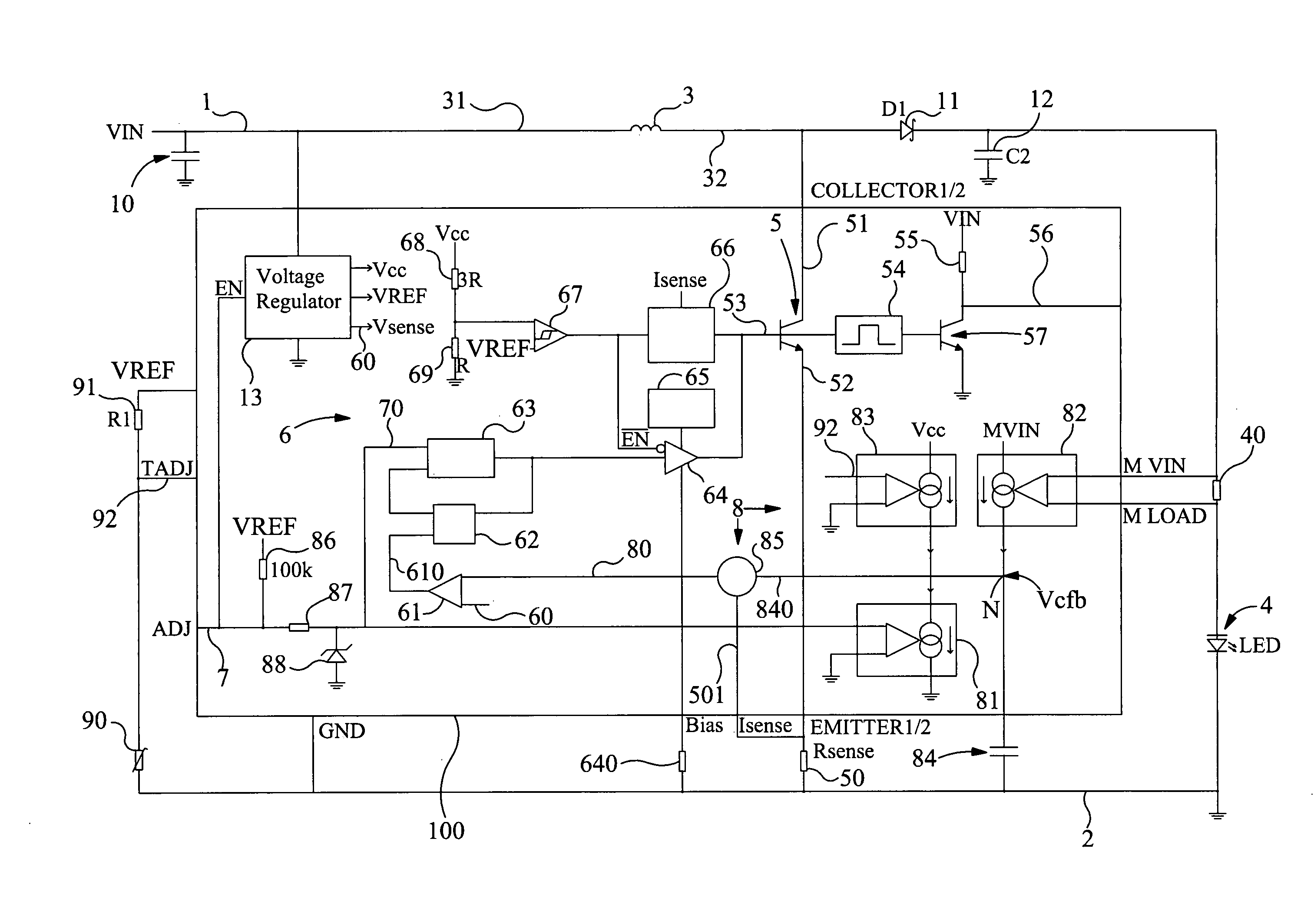
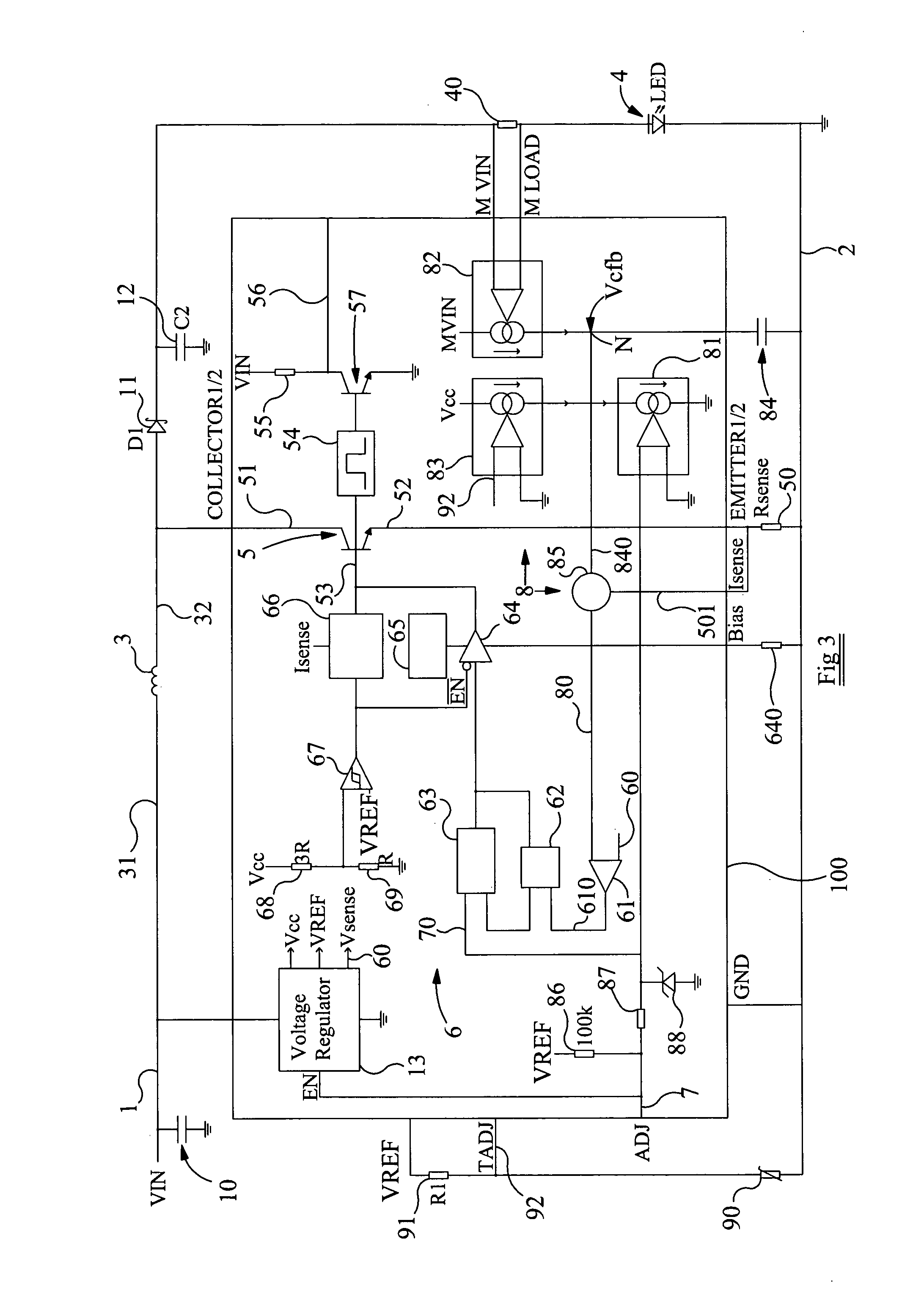
[0116]Referring now to FIG. 3, this shows a circuit embodying the invention, which can also be described as a drive circuit embodying the invention, arranged to drive a load 4. The circuit comprises a first supply rail 1 and a second supply rail 2 for connection to a dc power supply, providing a supply voltage Vin. An input capacitor 10 is connected between the supply voltage input and ground. An inductor 3 (L1) has a first inductor terminal 31 connected to the first supply rail 1, and has a second inductor terminal 32. A load 4 is connected in series with load current monitor resistor 40 (RM) between the second inductor terminal 32 and the second supply rail 2. In series with the load 4 is a diode 11, and an output capacitor 12 is connected in parallel with the load and RM, between the diode 11 and ground. In this embodiment the load 4 is a 3 W LED. The circuit also comprises a controllable switching device, in the form of a bipolar transistor 5, and ...


PUM


Abstract

A circuit comprises an inductor, a load, and a controllable switching device arranged in either a first configuration: switchable between the load being bypassed and the inductor energised, and current flowing through the load, and the inductor discharging energy into the load; or, a second configuration: switchable between current being permitted to flow through the load, inductor and controllable switching device in series, energising the inductor, and the current flowing through the load, and the inductor discharging energy into the load. The circuit further comprises control means for controlling the switching device, a load current sensing resistor connected in series with the load, and a demand signal input. Monitoring means is arranged to monitor the demand signal and the voltages across the sense resistors, and generate a monitor signal. The control means is arranged to receive the monitor signal and to switch the switching device in response the monitor signal exceeding a predetermined threshold.

Description

FIELD OF THE INVENTION[0001]The present invention relates to methods of driving a current through a load, and to circuits in which a current is driven through a load. In particular, although not exclusively, embodiments of the invention relate to the controlled driving of LEDs.BACKGROUND TO THE INVENTION[0002]For a variety of applications there is a requirement for a drive circuit able to provide regulated drive of a load from some dc power supply. One such drive circuit in accordance with the prior art is shown in FIG. 1 and incorporates a Zetex Semiconductors plc. voltage mode boost converter ZXSC410. The circuit may, for example, be connected to a battery power supply and is able to provide a regulated output voltage Vout to drive an attached load. Applications of the circuit include the provision of system power for battery-operated portable products, the biasing of LCDs, and local voltage conversion. Further details of the converter device are shown in FIG. 2. Operation of the ...

Claims


Application Information

Patent Timeline
IPC IPC(8): H02M3/156G05F1/10H05B44/00
CPCH05B33/0815H02M3/156H05B45/3725H05B45/395Y02B20/30G05F1/62H05B45/00
Inventor TAYLOR, CRAIGMASON, HOWARD
Owner ZETEX SEMICON PLC
Why Eureka
Try Eureka