
Methods and systems for deploying seismic devices

a technology of seismic devices and methods, applied in the direction of mechanical vibration separation, instruments, borehole/well accessories, etc., can solve the problems of large system size, high cost, limited life of instruments,

Inactive Publication Date: 2010-08-05
SCHLUMBERGER TECH CORP
View PDF18 Cites 22 Cited by
  • Summary
  • Abstract
  • Description
  • Claims
  • Application Information

AI Technical Summary

Benefits of technology

[0016]Additionally, applicants recognized a need for seismic source devices that generate seismic signals efficiently with repeatability, and have suitable source bandwidth, for example, low frequency acoustic energy for deep imaging. Additionally, applicants recognized that the ability to remove seismic devices from the downhole locations and to return them to the original position(s) provides significant advantages in semi-permanent / permanent reservoir monitoring operations.

Problems solved by technology

However, an instrument has limited life and eventually it fails.
If the instrument is retrieved from its deployed position, for example, for maintenance, it is not possible to easily re-deploy the instrument at the same location, in the same orientation and with the same coupling condition.
This poses a problem in long term monitoring operations.
Such systems are very large in size and costly.
However, seismic sources need comprehensive maintenance and support.
Therefore, conventional seismic sources are often not suitable for permanent or semi-permanent deployment to monitor subsurface reservoirs.
Available downhole seismic instrumentation tends to be fragile and may not last for an extended period of time without periodic maintenance.
Downhole seismic instruments are expensive, and it is wasteful to permanently deploy them in a borehole if their use is limited.

Method used


Image

  • Methods and systems for deploying seismic devices
  • Methods and systems for deploying seismic devices
  • Methods and systems for deploying seismic devices

Examples


Embodiment Construction

[0047]Illustrative embodiments and aspects of the invention are described below. It will of course be appreciated that in the development of any such actual embodiment, numerous implementation-specific decisions must be made to achieve the developers' specific goals, such as compliance with system-related and business-related constraints, that will vary from one implementation to another. Moreover, it will be appreciated that such development effort might be complex and time-consuming, but would nevertheless be a routine undertaking for those of ordinary skill in the art having the benefit of this disclosure.

[0048]Reference throughout the specification to “one embodiment,”“an embodiment,”“some embodiments,”“one aspect,”“an aspect,” or “some aspects” means that a particular feature, structure, method, or characteristic described in connection with the embodiment or aspect is included in at least one embodiment of the present invention. Thus, the appearance of the phrases “in one embo...


PUM


Abstract

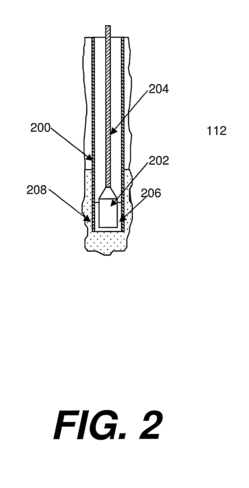
Methods and systems for acoustically determining reservoir parameters of subterranean formations. A tool comprising at least one seismic source or seismic receiver mounted thereon; a conveyance configured for movement of the acoustic tool in a borehole traversing the subterranean formations; and a source retainer configured or designed for permanent deployment in the borehole to removably retain the acoustic tool in the borehole. The source retainer when deployed provides acoustic coupling with the borehole and removably retains the acoustic tool in the borehole so that, over multiple deployments, the acoustic tool is repeatedly deployed at the same predetermined location and orientation relative to the subterranean formation, and with the same acoustic coupling to the borehole.

Description

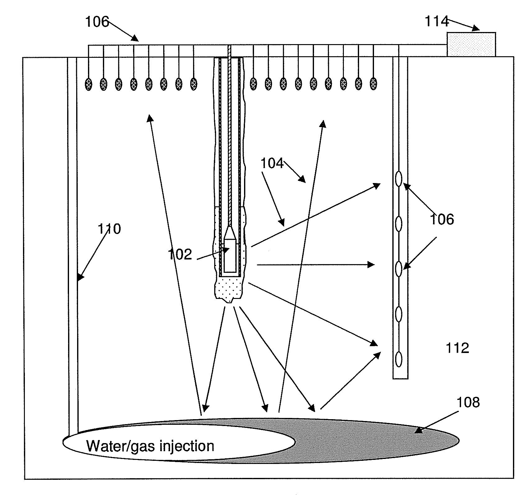
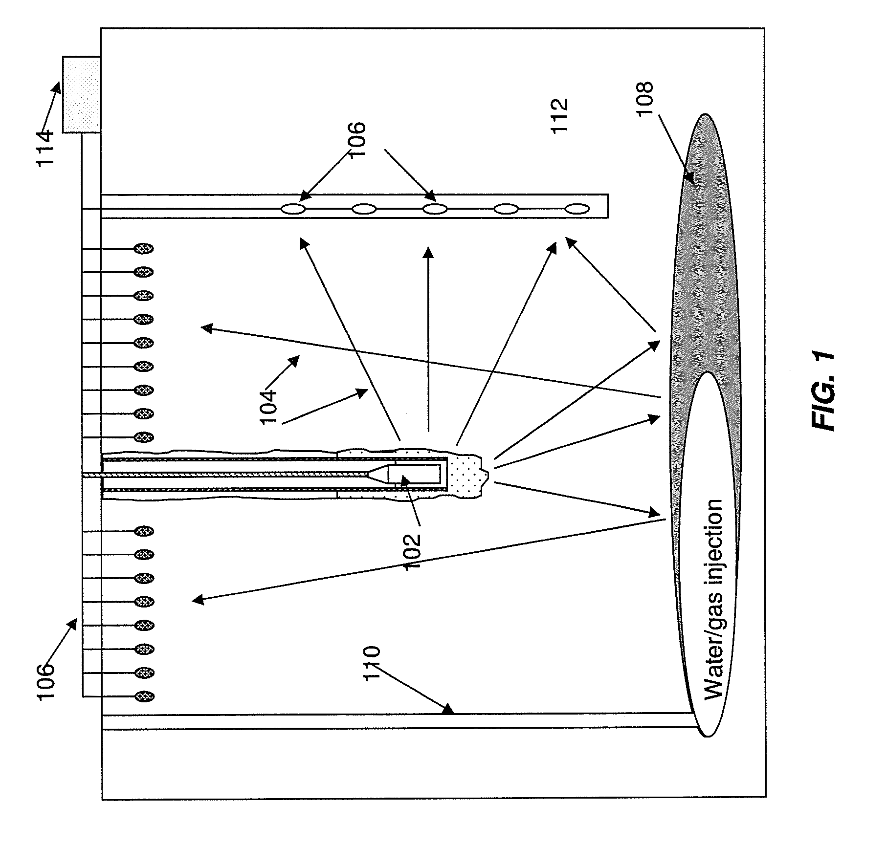
BACKGROUND[0001]1. Field of the Invention[0002]The present disclosure relates generally to methods and systems for performing acoustic measurements of subterranean formations. More specifically, some aspects disclosed herein are directed to methods and systems for deploying seismic devices, such as seismic sources and / or receivers, in a borehole for characterizing subterranean formations having, for example, oil and / or gas deposits therein. The methods and systems utilize permanent downhole installations that removably retain retrievable seismic tools having one or more seismic instrumentation such that the seismic instrumentation has a fixed location and orientation relative to the subterranean formations.[0003]2. Background of Related Art[0004]Seismic exploration can provide valuable information useful in the drilling and operation of oil and gas wells. Seismic measurements of the type described herein are also useful in the fields of CO2 sequestration, development of methane hydr...

Claims


Application Information

Patent Timeline
Patent Type & Authority Applications(United States)
IPC IPC(8): G01V1/44G01V1/38
CPCG01V1/44E21B49/00E21B23/00E21B23/01E21B23/02E21B49/087G01V1/52
Inventor KAMATA, MASAHIROKIMURA, TSUNEHISA
Owner SCHLUMBERGER TECH CORP
Learn More